LCO-IV------------------------------------------------------------------
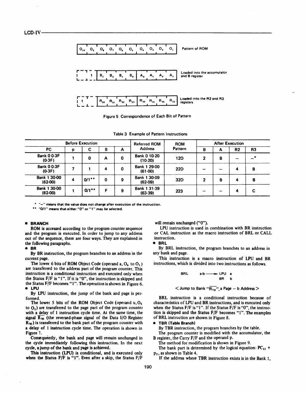
Pattern of
AOM
Loaded into the accumulator
and B register
Figure 5 Correspondence of
Each
Bit of Pattern
Table 3 Example of Pattern Instructions
Before Execution
Referred
ROM
ROM
After Execution
PC
p
C B A
Address
Pattern
B
A R2
R3
Bank
00-3F
1
0 A 0
Bank 0 10-20
120
2 B
.
(0-3F)
(10-20)
- -
Bank
00-3F
7 1
4
0
Bank 1 29-00
220
4
B
(0-3F)
(61-00)
- -
Bank
1 30-00
4
0/1··
0 9
Bank 1
30-09
320
2 B
4
B
(62-00)
(62-09)
Bank
1 30-00
1
0/1**
F
9
Bank
131-39
223
4
C
(62-00)
(63-39)
-
-
•
"-"
means
that
the value does
not
change after execution
of
the instruction.
"0/1"
means
that
either
"0"
or
"1"
may be selected.
•
BRANCH
ROM
is accessed according to the program counter sequence
and the program
is
executed. In order
to
jump
to
any address
out
of
the sequence, there are four
ways_
They are explained in
the following
paragraphs_
•
BR
By
BR
instruction, the program branches to
an
address in the
current page.
The lower
6 bits
of
ROM
Object Code (operand a, 0
6
to 0
1
)
are transferred to the address part
of
the program counter. This
instruction
is
a conditional instruction and executed only when
the
Status F
IF
is
"1".
If
it
is
"0",
the instruction is skipped and
the
Status F
IF
becomes" 1". The operation
is
shown
in
Figure 6.
•
LPU
By
LPU
instruction, the jump
of
the bank and page is per-
formed.
The lower 5 bits
of
the
ROM
Object Code (operand u,Os
to
0.)
are
transferred
to
the page part
of
the program counter
with a delay
of
1 instruction cycle time. At the same time, the
signal
R?O
(the reversed-phase signal
of
the Data
1/0
Register
R?O)
is transferred
to
the bank part
of
the program counter with
a delay
of
1 instruction cycle time. The operation
is
shown in
Figure
7_
Consequently, the bank and page will remain unchanged in
the cycle immediately following this instruction. In the next
cycle, a jump
of
the bank and page
is
achieved.
This instruction (LPU) is conditional, and is executed only
when the
Status
F/F
is
"I".
Even after a skip, the Status
F/F
190
will remain unchanged
("0").
LPU
instruction
is
used in combination with BR instruction
or
CAL instruction
as
the macro instruction
of
BRL
or
CALL
instruction.
• BRL
By
BRL instruction, the program branches to an address in
any bank and page.
This insiruction
is
a macro instruction
of
LPU
and
BR
instructions, which
is
divided into two instructions
as
follows.
BAL
a-b-
LPU a
BA b
<Jump
to
Bank
"R,o",a
Page
- b Address >
BRL instruction
is
a conditional instruction because
of
characteristics
of
LPU
and BR instructions, and
is
executed only
when the
Status F
IF
is
"I
".
I f the Status F
IF
is
"0",
the instruc-
tion is skipped and the Status F
IF
becomes
"1".
The examples
of
BRL instruction are shown
in
Figure 8.
• TBR (Table Branch)
By
TBR instruction, the program branches by the table.
The program counter
is
modified with the accumulator, the
B register, the
Carry
F/F
and the operand
p-
The method for modification
is
shown in Figure 9.
The bank part
is
determined by the logical equation:
PClI
+
P2,
as
shown
in
Table 4.
If
the address where TBR instruction exists
is
in the Bank
1,


 To Next Page
 Loading...


