--------------------------------------------------------------HMCS404C
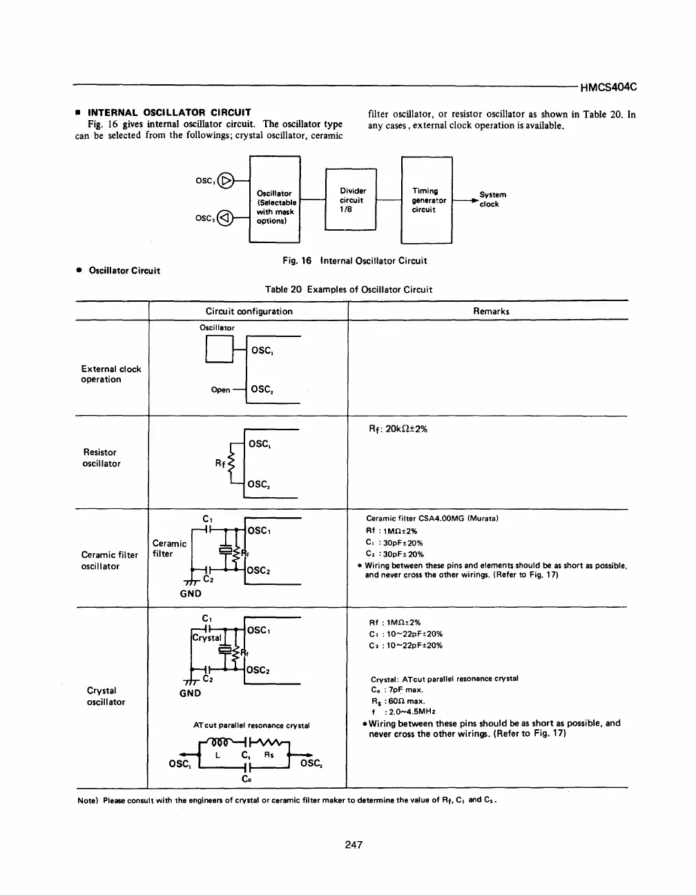
• INTERNAL OSCILLATOR CIRCUIT
Fig. 16 gives
internal
oscillator
circuit.
The
oscillator
type
can
be
selected
from
the
followings;
crystal
oscillator,
ceramic
filter
oscillator,
or
resistor
oscillator
as
shown
in
Table
20.
In
any
cases,
external
clock
operation
is available.
OSC.
[>
OSC.
<J
Oscillator
(Selectable
with mask
options)
Divider
circuit
1/8
Timing
generator
circuit
Fig.
16
Internal
Oscillator
Circuit
System
clock
•
Oscillator
Circuit
External
clock
operation
Resistor
oscillator
Ceramic
filter
oscillator
Crystal
oscillator
Table
20
Examples
of
Oscillator
Circuit
Circuit
configuration
Oscillator
D-OSC,
Open-
OSC.
e
sc.
Rf
OSC.
cerami1~~~
OSC,
filter
T~
:F
f
L~""OSC2
C2
~
______
_
GND
ATcut parallel resonance crystal
~,~
O~f--2-IOsC.
Co
Remarks
Rf:
20kn±2%
Ceramic filter
CSA4.00MG
(Murata)
Af
:
1MO±2%
C.
: 30pF±20%
C
,
: 30pF±
20%
• Wiring between these pins and elements should
be
as
short
as
possible,
and never cross the other wirings. (Refer to
Fig.
17)
Af
:
1MO±2%
C. : 10-22pF±20%
C.
: 10-22pF±20%
Crystal:
ATcut parallel resonance crystal
Co
: 7pF max.
As
:600
max.
f :
2.0-4.SMHz
.Wiring
between
these
pins
should
be as
short
as possible,
and
never cross
the
other
wirings.
(Refer
to
Fig. 17)
Note) Please consult with the engineers of crystal or ceramic filter maker
to
determine the value of
Af,
C.
and C
•.
247



 To Next Page