EasyManua.ls Logo

Hitachi AP1 - Page 303

Hitachi AP1
378 pages
Print Icon
To Next Page IconTo Next Page
To Previous Page IconTo Previous Page
Loading...
--------------------------------------------------------------------------HMcS~4AC
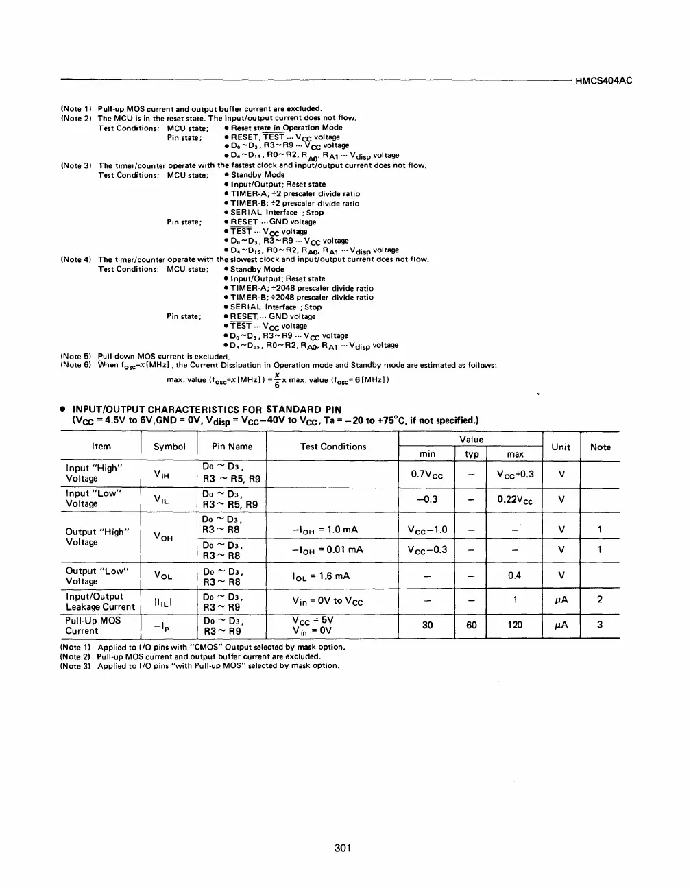
(Note
1)
Pull-up
MOS
current
and
output
buffer
current
are excluded.
(Note
2) The
MCU
is
in the reset state.
The
input/output
current
does
not
flow.
Test
Conditions:
MCU
state; • Reset state
in
Operation
Mode
Pin state; • RESET,
TEST
...
Vee
voltage
•
D.
-0"
R3-
R9
'"
Vee
voltage
•
D.-DIS,
RO-R2,
RAQ'
RA1'"
Vdisp
voltage
(Note 3)
The
timer/counter
operate
with
the
fastest
clock
and
input/output
current
does
not
flow.
Test
Conditions:
MCU
state; •
Standby
Mode
•
Input/Output;
Reset state
•
TIMER-A;
+2
prescaler
divide
ratio
•
TIMER-S;
+2
prescaler
divide
ratio
• SER
IAL
Interface ;
Stop
Pin state; •
RESET
..
·GND
voltage
•
TEST
...
Vee
voltage
•
0.-0"
R3-R9
.. ·
Vee
voltage
•
D.
-DIS,
RO-R2,
RAQ, RA1 ...
Vdisp
voltage
(Note
4)
The
timer/counter
operate
with
the
slowest
clock
and
input/output
current
does
not
flow.
Test
Conditions:
MCU state; •
Standby
Mode
•
Input/Output;
Reset state
•
TIMER-A;
+2048
prescaler
divide
ratio
•
TIMER-S;
+2048
prescaler
divide
ratio
•
SERIAL
Interface;
Stop
Pin state; • RESET. .. ·
GND
voltage
•
TEST
...
Vee
voltage
•
D.
-0"
R3-
R9 ... V
cc
voltage
•
D.
-DIS,
RO-
R2,
RAQ, RA1 .. , V disp voltage
(Note
5) Pull-down MOS
current
is
excluded.
(Note
6) When
fosc=x[MHz]
, the
Current
Dissipation in Operation
mode
and Standby
mode
are estimated
as
follows:
max.
value (fosc=X
[MHz]
)
=~x
max. value (fosc= 6
[MHz])
• INPUT/OUTPUT CHARACTERISTICS FOR STANDARD PIN
(Vee
= 4.5V
to
6V,GND =
OV,
Vdisp =
Vee-40V
to
Vee,
Ta
=
-20
to
+75°C,
if
not
specified.)
Item Symbol
Pin
Name Test Conditions
Input
"High"
V
IH
Do
-
03,
Voltage
R3
-
R5,
R9
Input
"Low"
V
IL
Do
-
03,
Voltage
R3-
R5,
R9
00
-
03,
Output
"High"
V
OH
R3-
R8
-loH
= 1.0
mA
Voltage
Do
-
03,
-IOH
= 0.01
mA
R3-
R8
Output
"Low"
VOL
00
-
03,
IOL
= 1.6
mA
Voltage
R3-
R8
Input/Output
\lILI
00
-
03,
Yin =
OV
to
VCC
Leakage
Current
R3-
R9
Pull-Up
MOS
-Ip
00
-
03,
Vee - 5V
Current
R3-
R9 Yin =
OV
(Note
1)
Applied
to
I/O
pins
with
"CMOS"
Output
selected
by
mask
option.
(Note
2) Pull-up MOS
current
and
output
buffer
current
are excluded.
(Note
3)
Applied
to
I/O
pins
"with
Pull-up
MOS"
selected
by
mask
option.
301
Value
min
typ
0.
7V
ee -
-0.3
-
Vee-
1
.
O -
Vee-
0
.
3 -
-
-
-
-
30 60
Unit
Note
max
Vee+
0
.
3 V
0.
22V
ec
V
-
V
1
- V 1
0.4
V
1
p.A
2
120
p.A
3