EasyManua.ls Logo

Hitachi AP1 - Page 306

Hitachi AP1
378 pages
Print Icon
To Next Page IconTo Next Page
To Previous Page IconTo Previous Page
Loading...
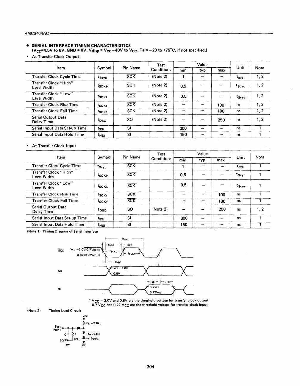
HMCS404AC--------------------------------------------------------------------------
•
SERIAL
INTERFACE
TIMING
CHARACTERISTICS
(Vee=4.5V
to
6V,
GND =
OV,
Vdisp =
Vee-40V
to
Vee,
Ta =
-20
to
+75°C,
if
not
specified.)
•
At
Transfer Clock
Output
Test
Value
Item
Symbol
Pin
Name
Conditions
min
typ
Transfer Clock Cycle Time
tSCyc
SCK
(Note 2)
1
-
Transfer Clock
"High"
tSCKH
SCK
(Note
2)
0.5
-
Level
Width
Transfer
Clock
"Low"
tSCKL
SCK
(Note
2)
0.5
-
Level
Width
Transfer
Clock
Rise
Time
tSCKr
SCK
(Note
2)
-
-
Transfer Clock Fall Time
tSCKf
SCK
(Note
2)
-
-
Serial
Output
Data
toso
SO
(Note 2)
-
-
Delay Time
Serial
Input
Data Set-up Time
tSSI
SI
300
-
Serial
Input
Data Hold Time t
HSI
SI
150
-
•
At
Transfer Clock
Input
Test
Value
Item
Symbol
Pin Name
Conditions
min
typ
Transfer Clock Cycle Time
tSCYC
SCK
1
-
Transfer Clock
"High"
tSCKH
SCK
0.5
-
Level Width
Transfer
Clock
"Low"
tscKL
SCK
0.5
-
Level
Width
Transfer
Clock
Rise
Time
tSCKr
SCK
-
-
Transfer Clock Fall Time
tSCKf
SCK
- -
Serial
Output
Data
toso
SO
(Note 2)
-
-
Delay Time
Serial
Input
Data Set-up Time
tSSI
SI
300
-
Serial
Input
Data Hold Time
tHSI
SI
150
-
(Note 1)
Timing
Diagram
of
Serial Interface
5CK
Vee
-2:0V(07Vee
'.
0.8V(O.22Vce) •
so
SI
H
ISS'
____
-«
0.7Vcc
'-____
O.22Vcc
*
Vee
- 2.0V and
O.BV
are
the threshold voltage
for
transfer
clock
output.
0.7
Vee
and 0.22
Vee
are
the threshold voltage
for
transfer
clock
inpu!.
(Note 2)
Timing
load
Circuit
Vee
15207418)
or
Equiv.
304
Unit
Note
max
-
tCYC
1,2
-
tSCYC
1,2
-
tscyC
1,2
100
ns
1,2
100
ns
1,2
250
ns
1,2
-
ns
1
-
ns
1
Unit
Note
max
-
tCYC
1
-
tSCYC
1
-
tscyC
1
100
ns
1
100
ns
1
250
ns
1,2
-
ns
1
-
ns
1