-----------------------------------------------------------------------HMCS404AC
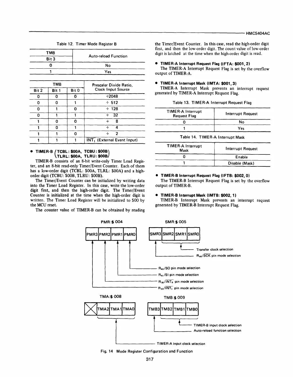
Table 12. Timer Mode Register B
TMB
Bit
3
Auto-reload Function
o
No
Yes
TMB
Prescaler
Divide Ratio,
Bit
2
Bit
1
Bit
0
Clock
Input
Source
0
0 0
+2048
0 0
1 512
0
1 0
128
0
1 1
32
1
0
0
8
1
0 1
4
1
1
0
2
1
1 1
INTI
(External Event Input)
•
TIMER-8
(TCBL:
$OOA,
TC8U:
$OOB)
TLRL:
$OOA,
TLRU:
$008
TIMER-B consists
of
an 8-bit write-only Timer Load Regis-
ter, and an 8-bit read-only Timer/Event Counter. Each
of
them
has a low-order digit (TCBL:
$OOA,
TLRL:
$OOA)
and a high-
order digit (TCBU:
$OOB,
TLRU:
$OOB)_
The Timer/Event Counter can be initialized
by
writing data
into the Timer Load Register. In this case, write the low-order
digit first, and then the high-order digit. The Timer/Event
Counter
is
initialized at the time when the high-order digit
is
written. The Timer Load Register will be initialized to $00 by
the
MCU
reset.
The counter value
of
TIMER-B can be obtained
by
reading
PMR:$
004
the Timer/Event Counter. In this case, read the high-order digit
first, and then the low-order digit.
The
count
value
of
low-order
digit
is
latched at the time when the high-order digit
is
read.
• TIMER-A Interrupt Request
Flag
(IFTA:
$001,2)
The TIMER-A Interrupt Request Flag
is
set
by
the overflow
output
of
TIMER-A.
• TIMER-A Interrupt Mask (IMTA:
$001,3)
TIMER-A Interrupt Mask prevents an interrupt request
generated by TIMER-A Interrupt Request Flag.
Table 13.
TIMER-A
Interrupt Request
Flag
TIMER-A Interrupt
Request
Flag
o
I nterrupt Request
No
Yes
Table 14.
TIMER-A
Interrupt
Mask
TIMER-A Interrupt
Mask
o
Interrupt Request
Enable
Disable (Mask)
• TIMER·B Interrupt Request
Flag
(IFTB:
$002,0)
The TIMER-B Interrupt Request Flag
is
set by the overflow
output
of
TIMER-B_
• TIMER-B Interrupt Mask (IMTB: $002, 1)
TIMER-B Interrupt Mask prevents an interrupt request
generated by TIMER-B Interrupt Request
Flag_
SMR:$005
Transfer clock selection
R
40
/SCK pin mode selection
L.-
_____
R42/S0
pin
mode selection
'---------
R
41
/SI pin mode selection
'------------
R3211NTo
pin mode selection
'--------------
R33/INTI
pin
mode selection
TMA:$
008
TMB:$009
I)<ITMA21TMA
11TMAOI
, . '
l'
L
TIMER-B
input
clock
selection
r l Auto-reload
function
selection
~
TlMER-A
input
clock
selection
Fig.
14
Mode Register Configuration
and
Function
317


 To Next Page
 Loading...



