EasyManua.ls Logo

Hitachi AP1 - Page 340

Hitachi AP1
378 pages
Print Icon
To Next Page IconTo Next Page
To Previous Page IconTo Previous Page
Loading...
HMCS404CL--------------------------------------------------------------------------
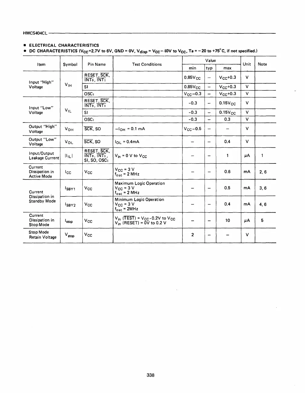
• ELECTRICAL CHARACTERISTICS
• DC CHARACTERISTICS
(Vee=2.7V
to
6V, GND =
av,
Vdisp =
Vee-4aV
to
Vee,
Ta
=
-20
to
+7SoC,
if
not
specified.)
Value
Item Symbol
Pin
Name
Test Conditions
Unit
Note
min
typ
max
RESET, SCK,
0.
85V
ee
-
Vee+
0
.
3
V
INTo,
INTI
Input
"High"
VIH
Voltage
SI
0.
85V
ee
-
Vee+
0
•
3
V
ascI
Vee-
0
.
3
-
Vee+
0
.
3
V
RESET, SCK,
-0.3
-
0.
15V
ee
V
Input
"Low"
INTo,
INTI
Voltage
VIL
SI
-0.3
-
0.
15V
ee
V
ascI
-0.3
-
0.3
V
Output
"High"
VOH
SCK,
so
-IOH
=
0.1
rnA
Voltage
Vee-
0
.
5
-
-
V
Output
"Low"
VOL
SCK,
SO
IOL
= O.4mA
- - 0.4
V
Voltage
Input/Output
RESET, SCK,
IIILI
INTo,
INTI,
V
in
= 0 V
to
Vee
- -
1
p.A
1
Leakage
Current
SI,
SO,
ascI
Current
Vee = 3 V
Dissipation in
lee Vee
- - 0.6
rnA
2,6
Active Mode
fasc
= 2 MHz
Maximum Logic Operation
ISBY1
Vee
Vee = 3 V
- -
0.5 rnA
3,6
Current
fasc
= 2 MHz
Dissipation in
Minimum Logic Operation
Standby Mode
ISBY2
Vee
Vee = 3 V
- -
0.4 rnA
4,6
fasc = 2MHz
Current
Vin
(TEST) =
Vee-0.2V
to
Vee
Dissipation in
I
stap
Vee
-
-
10
p.A
5
Stop Mode
Vin
(RESET) =
OV
to
0.2 V
Stop Mode
V
stap
Vee
2
-
-
V
Retain Voltage
338