---------------------------------------------------------------------------HMCS404CL
Instruction
Cycles
Instruction
execution
Interrupt
accepted
2
Stacking,
Reset
of
lIE
3
Stacking,
Vector address
is
generated
4
5
JMPL instruction execution on
the
vector address
6
Fig.
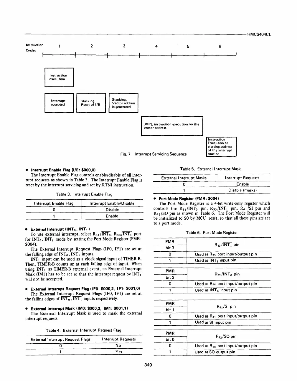
7 Interrupt Servicing Sequence
Instruction
Execution
at
starting address
of
the
interrupt
routine
• Interrupt Enable Flag (lIE: $000,0)
The Interrupt Enable Flag controls enable/disable
of
all inter-
rupt requests
as
shown in Table 3. The Interrupt Enable Flag
is
reset by the interrupt servicing and set by RTNI instruction.
Table 3.
Interrupt Enable
Flag
Interrupt Enable Flag I nterrupt Enable/Disable
o
Disable
Enable
• External Interrupt (INTo, INTI)
To use external interrupt, select
R32
/INT
o
,
R33
/INT I port
for INTo, INT
I mode by setting the Port Mode Register (PMR:
$004).
The External Interrupt Request Flags (lFO,
IF!)
are set at
the
falling edge
of
INT
0,
INT I inputs.
INT
I input can be used
as
a clock signal input
of
TIMER-B.
Then, TIMER-B counts up at each falling edge
of
input. When
using INTI
as
TIMER-B external event, an External Interrupt
Mask (1M!) has
to
be set
so
that the interrupt request by INTI
will
not
be
accepted.
• External Interrupt Request Flag (I
FO:
$000,2, I F1: $001,0)
The External Interrupt Request Flags (lFO,
IFl)
are set at
the falling edges
of
INT
0,
INT 1 inputs respectively.
• External Interrupt Mask
(lMO:
$000,3, IM1: $001,1)
The External Interrupt Mask
is
used
to
mask the external
interrupt requests.
Table
4. External Interrupt Request Flag
External
Interrupt Request Flags
Interrupt Requests
o
No
Yes
349
Table 5. External I nterrupt
Mask
External Interrupt
Masks
I nterrupt Requests
o
Enable
Disable (masks)
• Port Mode Register (PMR: $004)
The Port Mode Register
is
a 4-bit write-only register which
controls the
R32
/INT 0 pin,
R33
/INT I pin,
~
1 lSI pin and
~2
ISO pin
as
shown in Table 6.
The
Port Mode Register will
be initialized
to
$0 by
MCV
reset,
so
that
all
these pins are set
to
a port mode.
Table 6. Port Mode Register
PMR
R33/INTI pin
bit
3
0
Used
as
R33
port
input/output
pin
Used
as
INT
1 input pin
PMR
R32/INTo pin
bit 2
0
Used
as
R32
port
input/output
pin
Used
as
INTo
input pin
PMR
R
41
/SI pin
bit
1
0
Used
as
R41
port
input/output
pin
Used
as
51
input pin
PMR
bit 0
R42/S0
pin
0
Used
as
R42
port input/output pin
Used
as
SO
output
pin


 To Next Page
 Loading...



