---------------------------------------------------------------------------HMCS404CL
Do
GND
't"""""""
,--0---0-/
Fig. 17 Recommendable Layout
of
Crystal
and
Ceramic Filter
•
LOW
POWER
DISSIPATION MODE
The
MCU
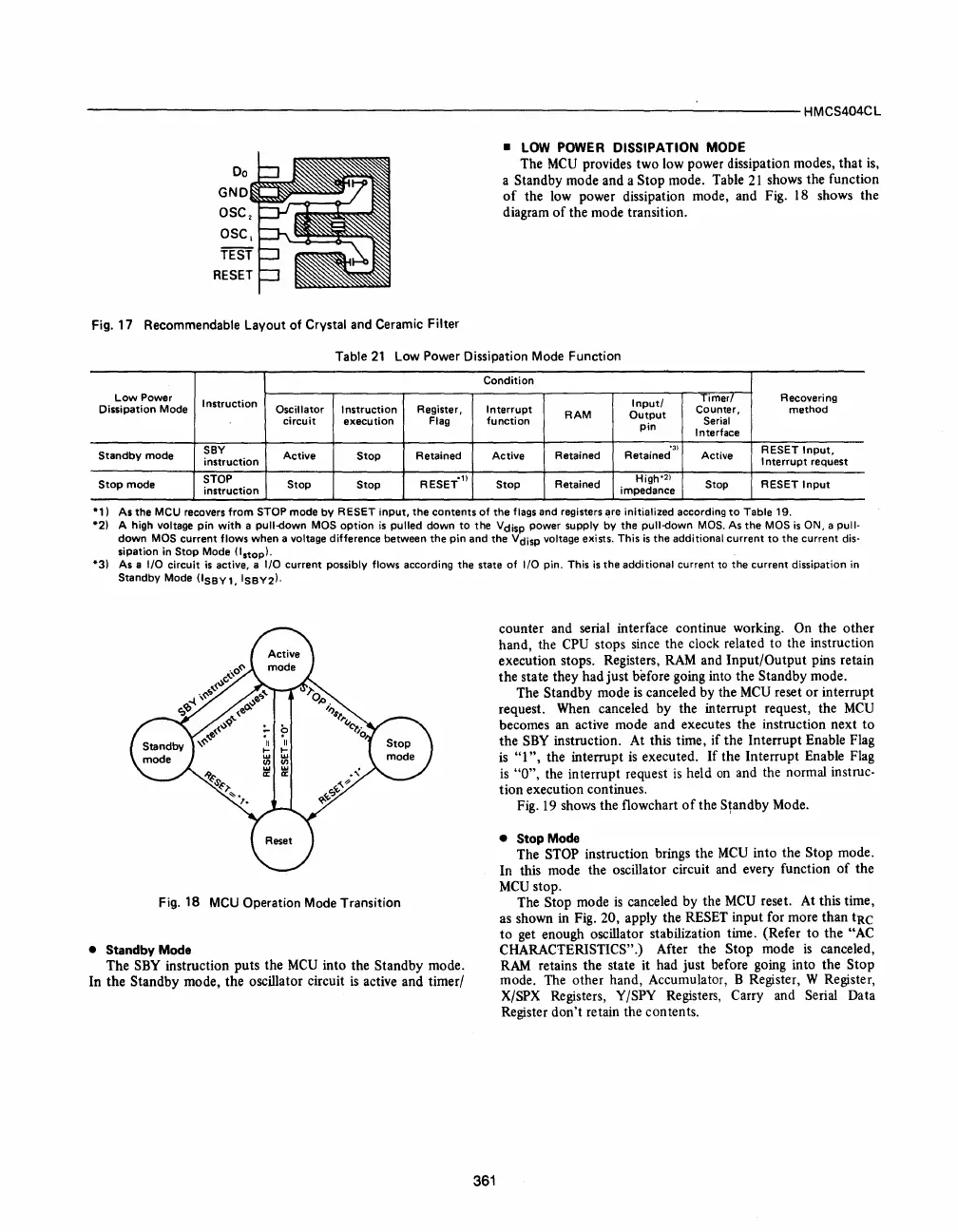
provides two low power dissipation modes, that
is,
a Standby mode and a Stop mode. Table
21
shows the function
of
the low power dissipation mode, and Fig.
18
shows the
diagram
of
the mode transition.
Table
21
Low Power Dissipation Mode Function
Condition
Low
Power
Instruction
Input/
Timer/
Recovering
Dissipation Mode
Oscillator
Instruction
Register,
Interrupt
Counter,
method
circuit
execution
Flag
function
RAM
Output
Serial
pin
Interface
Standby
mode
SBY
Active
Retained
Active
'3}
RESET
Input,
instruction
Stop
Retained Retained Active
Interrupt
request
Stop
mode
STOP
Stop
Stop
RESET'
ll
Stop
Retained
High'
2
)
Stop RESET
Input
instruction
impedance
*'
)
*2)
As
the
MCU recovers
from
STOP mode
by
RESET
input,
the
contents
of
the
flags and registers are initialized according
to
Table 19.
*31
A high voltage
pin
with
a
pull-down
MOS
option
is
pulled
down
to
the Vdisp power supply
by
the
pull-down
MOS. As
the
MOS
is
ON, a
pull·
down
MOS
current
flows
when a voltage difference between
the
pin
and the Vdisp voltage ellists.
This
is
the additional
current
to
the
current
dis·
sipation in Stop Mode
(Istop!.
As a
I/O
circuit
is
active, a
I/O
current possibly
flows
according the state
of
I/O
pin. This
is
the
additional
current to the current dissipation in
Standby Mode
(lSBY1,
ISBY2).
Fig. 18 MCU Operation Mode Transition
counter and serial interface continue working. On the other
hand, the
CPU
stops since the clock related
to
the instruction
execution stops. Registers,
RAM
and Input/Output pins retain
the state they had just before going into the
Standby mode.
The
Standby mode
is
canceled by the
MCU
reset or interrupt
request. When canceled by the interrupt request, the
MCU
becomes an active mode and executes the instruction next
to
the
SBY
instruction. At this time, if the Interrupt Enable Flag
is
"1",
the interrupt
is
executed.
If
the Interrupt Enable Flag
is
"0",
the interrupt request
is
held
on
and the normal instruc-
tion execution continues.
Fig.
19
shows the flowchart
of
the
S~andby
Mode .
• Stop
Mode
The STOP instruction brings the
MCU
into the Stop mode.
In this mode the oscillator circuit and every function
of
the
MCU
stop.
• Standby
Mode
The Stop mode
is
canceled by the
MCU
reset. At this time,
as
shown in Fig. 20, apply the RESET input for more than
tRe
to
get enough oscillator stabilization time. (Refer
to
the "AC
CHARACTERISTICS".)
After the Stop mode
is
canceled,
RAM
retains the state it had just before going into the Stop
mode. The other hand, Accumulator, B Register, W Register,
X/SPX Registers, Y/SPY Registers, Carry and Serial Data
Register don't retain the contents.
The
SBY
instruction puts the
MCU
into the Standby mode.
In the
Standby mode, the oscillator circuit
is
active and timer/
361


 To Next Page
 Loading...



