HMCS44C,HMCS44CL------------------------------------------------------
O.2V
Vcc----'I
tOFF
specifies the period when the power supply
is
OFF
in the case that a short break
of
the power supply occurs and the power supply ON/OFF
is
repeated.
Figure
22
Power Supply Timing
for
Built-in Reset Circuit
• HALT FUNCTION
When the HLT pin
is
set to
"0"
("Low" level), the internal
clock stops and all the internal statuses (RAM, the Registers, the
Carry
FIF,
the Status FIF, the Program Counter, and
all
the in-
ternal statuses) are held. Because
all
internal
logic
operation stop,
power consumption
is
reduced. There are
two
input/output
statuses
in
the Halt State. The user should specify either "En-
able"
or
"Disable" using a mask option at the time
of
ordering
ROM.
"Enable" 1 Output
........
The Status before the Halt State
is
held.
Pull up
MOS
...
ON
Input.
.........
No relation to
"Halt"
Since Pull up
MOS
is
ON, Pull up
MOS
current
flows
with output
"0"
("Low" level)
in
the Halt
State (NMOS;ON). When an input signal changes,
transmission current
flows
into an input circuit.
Also, current
flows
into Pull up
MOS.
These cur-
Vcc
________
~
m:T
rents are added to the Stand-by Supply Current
(or Halt Current).
"Disable"1output
........
High
Impedance
(NMOS,
PMOS:
OFF)
Pull up
MOS
...
OFF
Input.
.........
Input Circuit: OFF
Both input and output are at high impedance
state. Since an input circuit
is
OFF, any current
other than the Stand-by Supply Current (or Halt
Current) does not
flow
even if an input signal
changes.
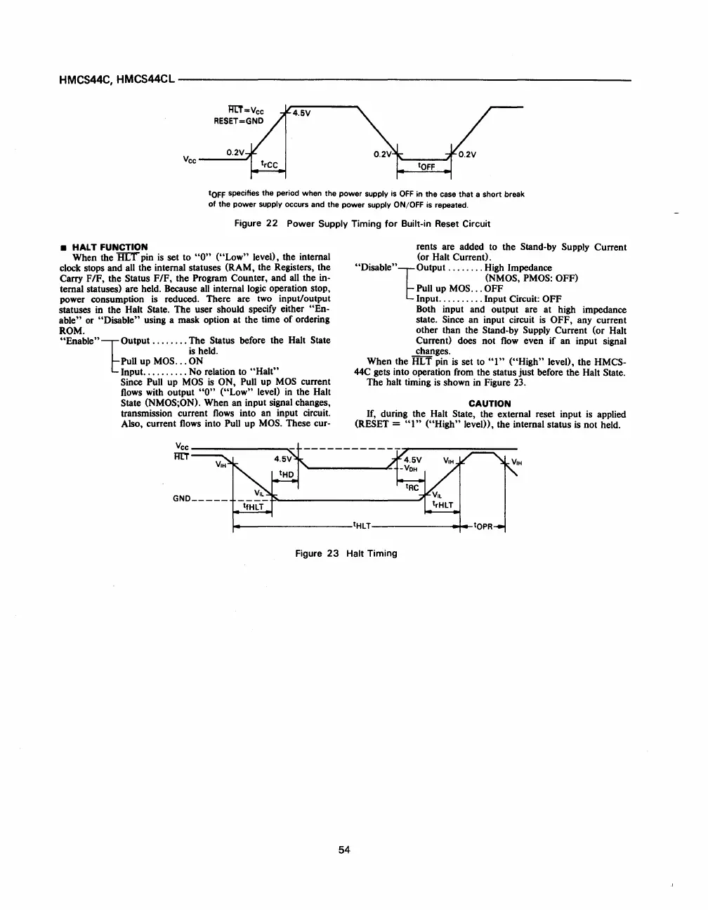
When the HLT pin
is
set to
"I"
("High" level), the HMCS-
44C gets into operation from the status just before the Halt State.
The halt timing
is
shown
in
Figure
23.
CAUTION
If, during the Halt State, the external reset input
is
applied
(RESET =
"I"
("High"
level),
the internal status
is
not held.
~-------------------tHLT--------------~
..
Figure
23
Halt Timing
54
 Loading...

