--------------------------------------------------------HMCS44C,HMCS44CL
No Pull up MOS
Vcc
I/O
Enable--r------j
I .
o---K
PMOS
I •
I I
L ______ J Input circuit
With
Pull up MOS (PMOS)
Vcc
I
I
I
I
I
I I
I I
L
______
J Input circuit
* When "Disable"
is
specified
for
the
I/O
State at the Halt State.
INTo
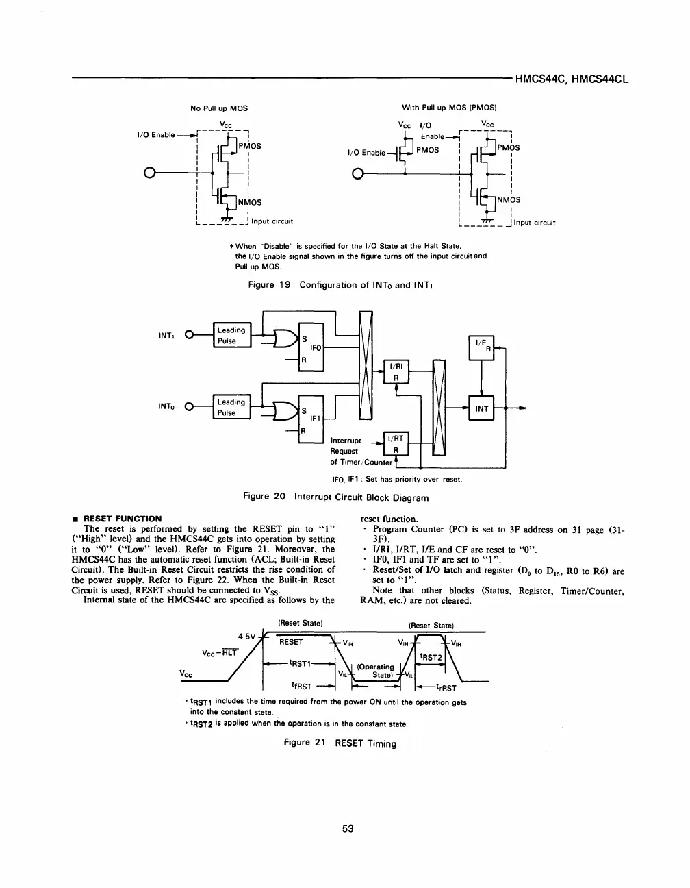
• RESET FUNCTION
the
I/O
Enable signal shown in the figure turns
off
the input circuit and
Pull up MOS.
Figure
19
Configuration
of
INTo and INT,
IFO.
IFl
: Set has priority over reset.
Figure
20
Interrupt Circuit Block Diagram
reset function.
The
reset
is
performed by setting
the
RESET pin to
"1"
("High"
level) and the HMCS44C gets into operation
by
setting
it to
"0"
("Low"
level). Refer to Figure 21. Moreover, the
HMCS44C has the automatic reset function (ACL; Built-in Reset
Circuit).
The
Built-in Reset Circuit restricts
the
rise condition
of
the
power supply. Refer to Figure 22.
When
the
Built-in Reset
Circuit
is
used, RESET should be connected to V ss.
Program Counter (PC)
is
set to
3F
address
on
31
page (31-
3F).
URI, IIRT,
liE
and
CF
are reset to
"0".
IFO,
IFI
and
TF
are set to
"1".
Reset/Set
of
110 latch
and
register
(Do
to DIS'
RO
to R6) are
set to
"1".
Note that other blocks (Status, Register, Timer/Counter,
RAM,
etc.) are
not
cleared.
Internal state
of
the
HMCS44C are specified as follows
by
the
Vee
•
tRSTl
includes the time required
from
the
power
ON
until the operation gets
into the constant state .
.
tRST2 is applied when the operation is in the constant state.
Figure
21
RESET
Timing
53
 Loading...

