--------------------------------------------------------HMCS46C,HMCS46CL
•
BRANCH
ROM
is accessed according to the program counter sequence
and the program is executed. In order
to
jump
to
any address
out
of
the sequence, there are four ways. They are explained in
the following paragraphs.
•
BR
By
BR instruction, the program branches
to
an address in the
current page.
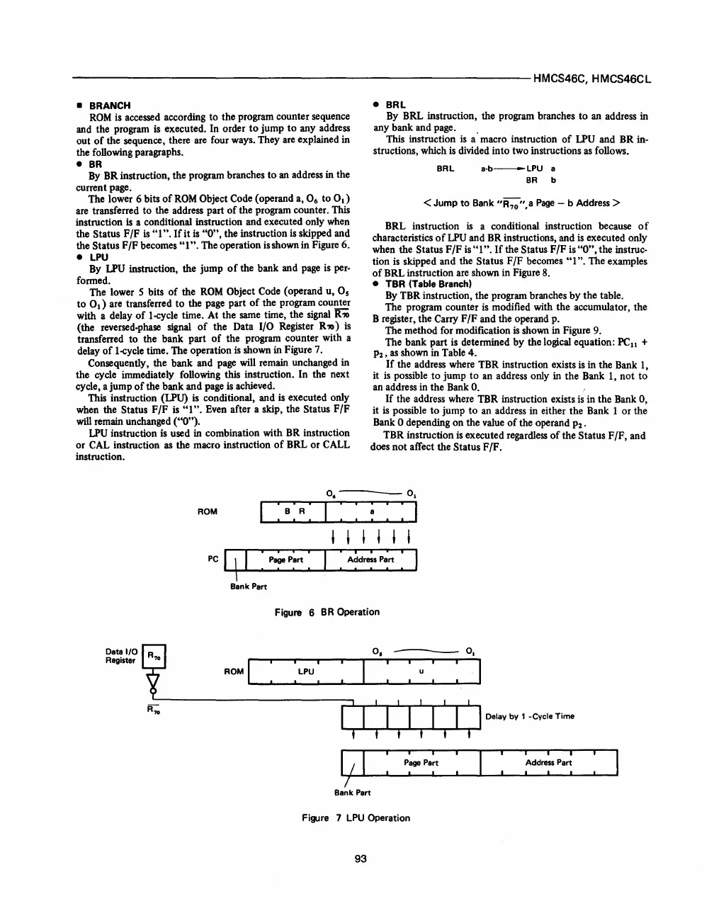
The lower 6 bits
of
ROM
Object Code (operand a, 0
6
to
0
1
)
are transferred
to
the address part
of
the program counter. This
instruction
is
a conditional instruction and executed only when
the Status
F/F
is
"I".
If
it
is
"0",
the instruction
is
skipped and
the Status
F/F
becomes
"1".
The operation
is
shown in Figure 6.
•
LPU
By
LPU
instruction, the jump
of
the bank and page
is
per-
formed.
The lower 5 bits
of
the
ROM
Object Code (operand u,
as
to
0
1
)
are transferred
to
the page part
of
the program
cou~
with a delay
of
1-cycle time. At the same time, the signal
R'70
(the reversed-phase signal
of
the Data 1/0 Register
R'70)
is
transferred to the bank part
of
the program counter with a
delay
of
1-cycle time. The operation
is
shown in Figure 7.
Consequently, the bank and
page
will remain unchanged in
the cycle immediately following this instruction.
In
the next
cycle, a jump
of
the bank and page
is
achieved.
This
instruction
(LPU)
is
conditional, and is executed only
when the Status
F/F
is
"I".
Even after a skip, the Status
F/F
will remain unchanged ("0").
LPU
instruction is used in combination with BR instruction
or
CAL
instruction
as
the macro instruction
of
BRL or CALL
instruction.
•
BRL
By BRL instruction, the program branches
to
an address in
any bank and page. .
This instruction
is
a macro instruction
of
LPU
and BR in-
structions, which
is
divided into two instructions
as
follows.
BRL
a-b-LPU
a
BR
b
< Jump
to
Bank
"R
70
",a
Page
- b Address >
BRL instruction is a conditional instruction because
of
characteristics
of
LPU
and BR instructions, and
is
executed only
when the Status
F/F
is
"1".
If
the Status
F/F
is
"0",
the instruc-
tion
is
skipped and the Status F
IF
becomes
"1".
The examples
of
BRL instruction are shown in Figure
8.
•
TBR
(Table Branch)
By
TBR instruction, the program branches
by
the table.
The program counter
is
modified with the accumulator, the
B register, the Carry
F/F
and the operand p.
The method for modification
is
shown in Figure 9.
The bank part
is
determined
by
the logical equation:
PC
11
+
P2,
as
shown in Table 4.
If
the address where TBR instruction exists
is
in the Bank 1,
it
is
possible
to
jump
to
an address only in the Bank 1,
not
to
an address in the Bank
O.
If
the address where TBR instruction exists
is
in the Bank 0,
it
is
possible
to
jump
to
an address in either the Bank I
or
the
Bank
0 depending on the value
of
the operand
P2
.
TBR instruction
is
executed regardless
of
the Status
F/F,
and
does not affect the Status F
IF.
ROM
I:
B :
R:
I : :
~
: : I
Data
1/0
Register
, , , , , ,
Figure 6
BR
Operation
0.-0.
I
Bank Part
Figure 7
LPU
Operation
93
Delay by 1 -Cycle Time
: I
 Loading...

