
L
Lisa DunnAug 14, 2025
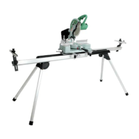
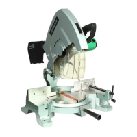
How to fix inaccurate cutting with Hitachi c15fb - 15 Amp Miter Saw No Bevel?
- SSamuel BrownAug 14, 2025
Inaccurate cutting with Hitachi Tools can stem from several issues. It could be due to improper perpendicularity between the vise and the base, causing inclined bevel cuts. Adjust or replace the vise to resolve this. Another cause might be the saw blade cutting at an angle because of issues between the saw blade and turn table. Try adjusting the M12 nut and lock nut to reduce any gap or vibration between the hinge and gear case, or replace the hinge, gear case, or turn table if they are damaged. Securing the turn table properly with the side handle can also prevent movement during cutting. If the vise or turn table surface is uneven, replacing them is recommended. Also, ensure that the workpiece is properly secured with the vise to prevent movement.