32
English
1. Remove the blade
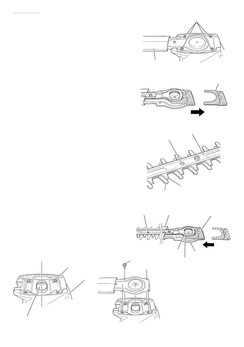
(1) Turn the tool over, remove the four screws
using a Phillips screwdriver, remove the bottom
plate and the blade (with blade case). (Fig. 6)
(2) Remove the spacer from the old blade.
(Remove any cutting or dust from inside of the
housing.) (Fig. 7)
2. Getting a new blade ready
(1) A hole (ø 5) used for positioning is located in
the center of the blade. Adjust the parts
including the upper and lower blades so that
the holes in these parts are aligned. (Fig. 8)
(2) When the parts are positioned correctly, attach
the blade case to the new blade.
(3) Insert the spacer, which was removed in above
step 1, between the upper and lower blades.
(Fig. 9)
3. Rotate the crank cam with your hand and
move it to the position shown in the fi gure.
(Fig. 10)
(1) Adjust the crank cam so that its circular disc
part comes just beside the unit as shown in
the fi gure.
(2) If the nuts (located in four positions) are loose,
press them into the groove of the housing.
4. Attach the new blade (Fig. 11)
(1) Align the central hole of the reversed new
blade holder with the rounded projection in the
center of the crank cam.
(2) With the spacer inserted between the blades,
fi x the blade holder using four screws.
Fig. 6
Screw
Blade case
Spacer
Fig. 7
Fig. 8
Lower blade
Upper blade
Holder plate
ø5 Hole
Fig. 9
Upper blade
Spacer
Blade holder
ø5 Hole
Blade case
Lower blade
Fig. 10
Housing
Nut
Crank cam
Fig. 11
Screw
000BookCH14DSLChS.indb32000BookCH14DSLChS.indb32 2017/04/1713:48:352017/04/1713:48:35





 To Next Page