EasyManua.ls Logo

Hitachi D-E10U - Adjustment; Inspection of Mechanism; Lubrication

Hitachi D-E10U
8 pages
Print Icon
To Next Page IconTo Next Page
To Previous Page IconTo Previous Page
Loading...
|
D-E10
0D-E10
|
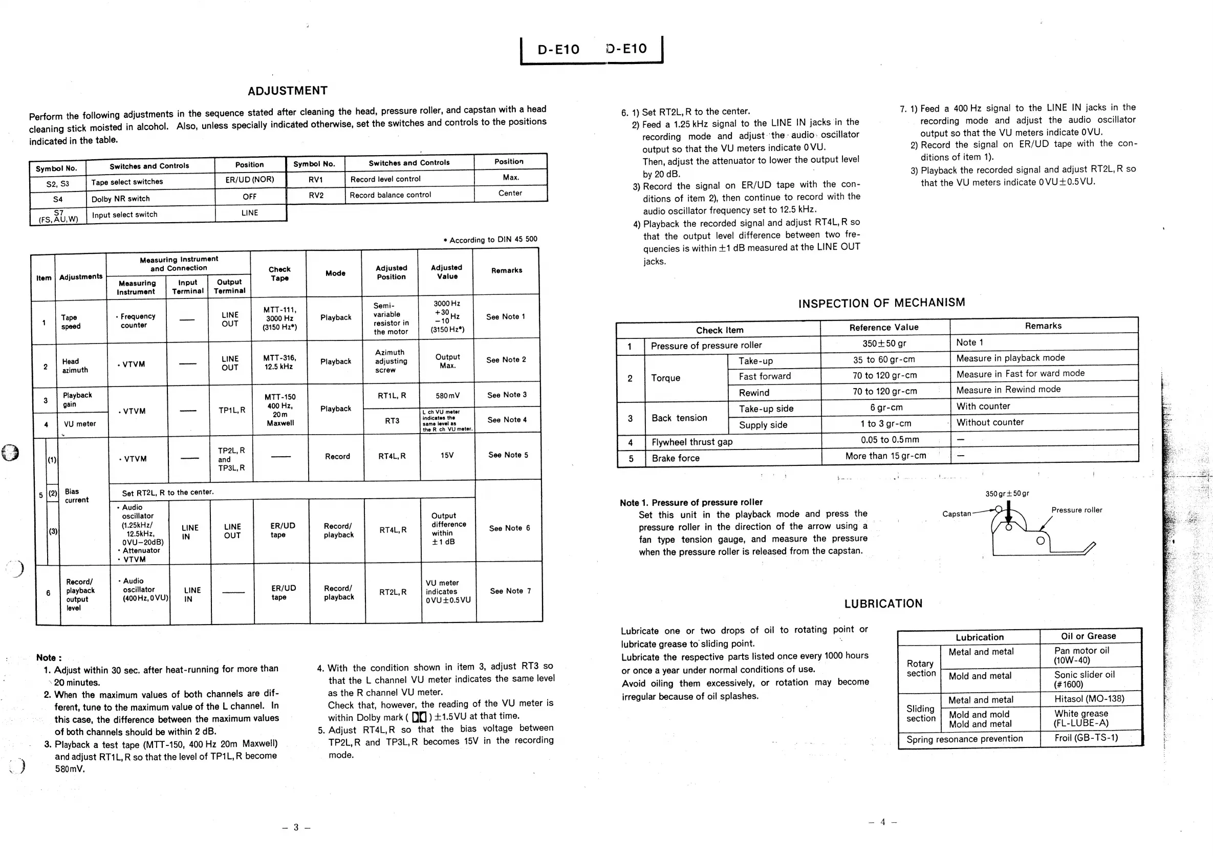
ADJUSTMENT
Perform
the
following
adjustments
in
the
sequence
stated
after
cleaning
the
head,
pressure
roller,
and
capstan
with
a
head
cleaning
stick
moisted
in
alcohol.
Also,
unless
specially
indicated
otherwise,
set
the
switches
and
controls
to
the
positions
indicated
in
the
table.
Switches
and
Controls
Tape
select
switches
$2,
S3
S4
Dolby
NR
switch
S
Input
select
switch
(FS,A
7
U,
W)
|
Con
LINE
Measuring
Instrument
and
Connection
Check
Symbol
No.
Switches
and
Controls
Record
level
control
Max,
|
*
According
to
DIN
45
500
Adjusted
Adjusted
6.
1)
Set
RT2L,
R
to
the
center.
9)
Feed
a
1.25
kHz
signal
to
the
LINE
IN
jacks
in
the
recording
mode
and
adjust-'the
-
audio:
oscillator
output
so
that
the
VU
meters
indicate
OVU.
Then,
adjust
the
attenuator
to
lower
the
output
level
by
20
dB.
3)
Record
the
signal
on
ER/UD
tape
with
the
con-
ditions
of
item
2),
then
continue
to
record
with
the
audio
oscillator
frequency
set
to
12.5
kHz.
4)
Playback
the
recorded
signal
and
adjust
RT4L,
R
so
that
the
output
level
difference
between
two
fre-
quencies
is
within
+1
dB
measured
at
the
LINE
OUT
jacks.
7.
1)
Feed
a
400
Hz
signal
to
the
LINE
IN
jacks
in
the
-
recording
mode
and
adjust
the
audio
oscillator
output
so
that
the
VU
meters
indicate
OVU.
9)
Record
the
signal
on
ER/UD
tape
with
the
con-
ditions
of
item
1).
3)
Playback
the
recorded
signal
and
adjust
RT2L,R
so
that
the
VU
meters
indicate
OVU+0.5VU.
Adjustments
Measuring
input
Output
Tape
Position
Instrument
Terminal
|
Terminal
MTT-111
Sent:
ae
INSPECTION
OF
MECHANISM
Tape
*
Frequency
LINE
3000
H
:
Siavhack
variable
+30),
counter
OUT
:
y
istor
i
-10'
7
See
Note
1
(3150
H2*)
resistor
in
ene
Lid
Head
LINE
Playback
~VTVM
TPIL,R
2,
Playback
:
20m
:
chy
Usnreter
Take-up
side
6
gr-cm
With
counter
:
VU
meter
Maxwell
RT3
indicates
the
See
Note
4
same
level
as
;
:
the
R
ch
VU
meter.
1
to
3
gr-cm
Without
counter
_
e
-_
PSs
ee
=
MTT-316,
12.5
kHz
Playback
Azimuth
adjusting
screw
=
Max.
||
_
La
Pressure
of
pressure
roller
i.
Torque
Take-up
Fast
forward
Flywheel
thrust
gap
|
Back
tension
Supply
side
Brake
force
35
35
to
70
to
120
gr-cm
0+50
gr
60
gr-cm
0.05
to
0.5mm
More
than
15
gr-cm
>
Bias
Set
RT2L,
R
to
the
center.
current
.
ee
=
Note
1.
Pressure
of
pressure
roller
Sci
.
:
7
(1.25kKHz/
ie
Output
Set
this
unit
in
the
playback
mode
and
press
the
(3)
KH
LINE
LINE
R/
Record/
RTAL.R
difference
See
Note
6
or
Ae
IN
OUT
tape
playback
cashin
e
pressure
roller
in
the
direction
of
the
arrow
using
a
_
;
AMenuato?
+1dB
fan
type
tension
gauge,
and
measure
the
pressure
—
-
VTVM
|
when
the
pressure
roller
is
released
from
the
capstan.
_
(400Hz,0VU)
level
|
Note:
| |
|
,
ee
:
4s
Lubricate
th
r
Metal
and
metal
Pan
motor
oil
1.
Adjust
within
30
sec.
after
heat-running
for
more
than
4.
With
the
condition
shown
in
item
3,
adjust
RT3
so
zc
pis
ne
aaa
ane
—
oe
every
1000
hours
Rony
(10W-40)
|
‘20
minutes.
|
that
the
L
channel
VU
meter
indicates
the
same
level
y
OF
Mab
CONGIBONS
Ohne:
_
2.
When
the
maximum
values
of
both
channels
are
dif-
ferent,
tune
to
the
maximum
value
of
the
L
channel.
In
this
case,
the
difference
between
the
maximum
values
of
both
channels
should
be
within
2
dB.
|
3.
Playback
a
test
tape
(MTT-150,
400
Hz
20m
Maxwell)
,
+
andadjust
RT1L,R
so
that
the
level
of
TP1L,R
become
.
—
580mV.
7
|
Record/
-
Audio
playback
oscillator
Record/
output
playback
LINE
ER/UD
IN
tape
VU
meter
RT2L,R
indicates
See
Note
7
0VU+0.5VU
as
the
R
channel
VU
meter.
Check
that,
however,
the
reading
of
the
VU
meter
is
within
Dolby
mark
(
{J
)
+1.5VU
at
that
time.
5.
Adjust
RT4L,R
so
that
the
bias
voltage
between
-
TP2L,R
and
TP3L,R
becomes
15V
in
the
recording
-
mode.
|
7
Note
1
Measure
in
playback
mode
Measure
in
Fast
for
ward
mode
LUBRICATION
Lubricate
one
or
two
drops
of
oil
to
rotating
point
or
lubricate
grease
to
sliding
point.
‘
Avoid
oiling
them
excessively,
or
rotation
may
become
irregular
because
of
oil
splashes.
_
|
Spring
resonance
prevention
section
|
Mold
and
metal
Sonic
slider
oil
(#1600)
|
:
Metal
and
metal
Hitasol
(MO-138)
Sliding
.
Mold
and
mold
White
grease
Mold
and
metal
(FL-LUBE-A)
Froil(GB-TS-1)
section