Do you have a question about the Hitachi D-E95 and is the answer not in the manual?
Essential safety measures for servicing and post-repair testing.
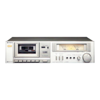
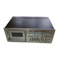
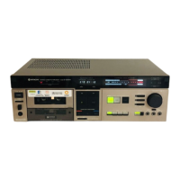
Detailed technical specifications of the D-E95 cassette tape deck.
Procedures for disassembling the cassette door, covers, and chassis.
Detailed steps and settings for calibrating various functions of the tape deck.
Guidelines for inspecting critical mechanical components and their specifications.
Recommended lubrication points and types of oil/grease for maintenance.
Visual layout of the Meter, Headphone, and Function Switch circuit boards.
Detailed electrical schematic illustrating the interconnected components of the device.
Visual representation of the main printed circuit board components and connections.
Visual layout of Power Switch, Timer Switch, Record Level, Peak Hold, and Auto Stop circuit boards.
Diagram illustrating the internal wiring and cable connections throughout the unit.
Exploded view of the main cabinet showing component placement and assembly.
Exploded view of the cassette chassis detailing component arrangement and assembly.
Comprehensive list of replacement parts with their part numbers and descriptions.
Continuation of the replacement parts list, including capacitors, resistors, semiconductors, and transformers.
Further replacement parts listing for cassette deck assembly and miscellaneous hardware.
Important safety guidelines for handling MOS integrated circuits to prevent damage.
Detailed explanation of the new microprocessor and motor driver circuitry.
Explanation of the tape end detection circuit and its interaction with the microprocessor.
Detailed description of solenoid driver and muting circuits for various functions.
Timing diagrams illustrating the operation of solenoids, motors, bias oscillator, and muting functions.
Sequence charts for auto recording muting and playback indication functions.
Step-by-step procedure for executing the device's built-in test program.
Detailed steps for troubleshooting using the test program and checking component logic.
Truth tables for test program outputs and button operation checks.
Detailed explanation of the input and output pin functions of the microprocessor IC2.
Continuation of IC2 pin function descriptions, detailing timer and motor control outputs.
Further details on IC2 pin functions, including tape end detector and reset inputs.