-5-
Reassembly can generally be conducted by reversing the disassembly procedure. However, special
attention should be given to the following items.
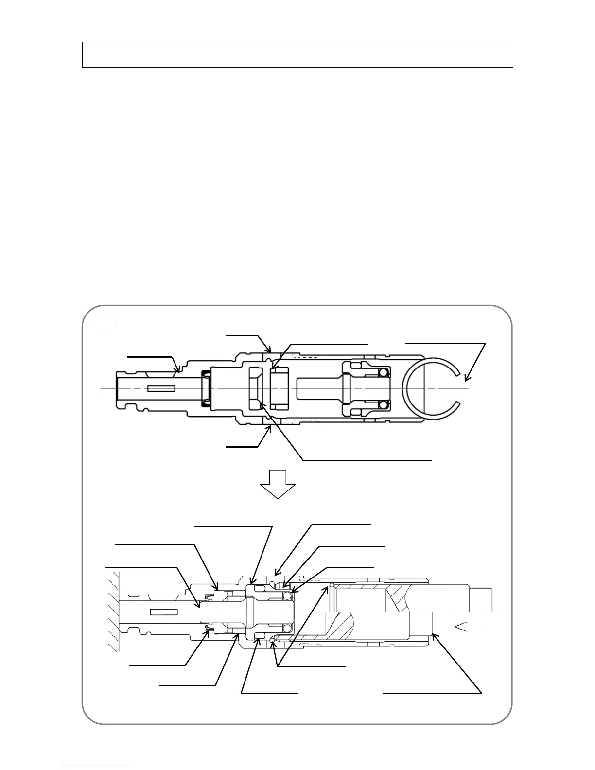
1. Reassembling the cylinder ass’y
Insert the set of Hammer Holder (C) [28], Sleeve (FW) [29], the Second Hammer [30], Hammer Holder
(A) [31], Damper (A) [32], O-ring (C) [33], and the Damper Holder [34] into the Cylinder [20] to which Oil
Seal (A) [27] is press-fitted. (Do not reverse the seal orientation.) (Assemble with the bore slope of
Hammer Holder (C) [28] set at the rear end and with the Sleeve (FW) [29] notch set at the front end as
shown in Fig. 5. Do not reverse the assembly order.) Push a new Stopper Ring [35] into the Cylinder [20]
with the break of the Stopper Ring [35] facing away from the ĭ8 hole on the Cylinder [20] as shown in Fig.
5. With the ring break facing toward the ĭ8 hole, the cylinder assembly is difficult to disassemble. Note the
ĭ8 hole on the Cylinder [20] and correctly orient the Stopper Ring [35] as shown in Fig. 5 when pushing in.
Insert stopper ring jig (A) (J-341) from the hole side and use a hand press to press against the upper end
of the jig until the Stopper Ring [35] is fitted into the bore groove of the Cylinder [20]. Confirm that the
Stopper Ring [35] is fit securely into the bore groove of the Cylinder [20] through the two ĭ8 holes on the
periphery of the Cylinder [20].
Reassembly
Fig. 5 Ɣ Inside structure of the cylinder ass’y
Hand press
Second Hammer [30]
Hammer Holder (C) [28]
Hammer Holder (A) [31]
Damper (A) [32]
Sleeve (FW) [29]
ĭ8 hole (2 holes)
Damper Holder [34]
O-ring (C) [33]
Stopper ring jig (A) (J-341)
Stopper Ring [35]
Oil Seal (A) [27]
Sleeve (FW) [29] notch
Cylinder [20]
ĭ8 hole
ĭ8 hole
Stopper Ring [35] break
Bore slope of Hammer Holder (C) [28]

 Loading...