K6602637
Rev.3
02.27.01
- 91 -
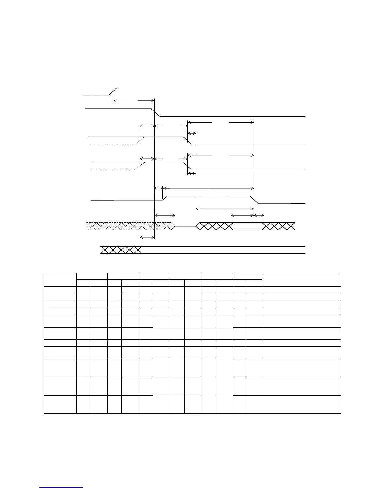
6.4.2 Ultra DMA Data Transfer Timing
Figures 6-8 through 6-12 and 6-13 through 17 define the timings associated with all phases of Ultra DMA data
transfer.
Figure 6-8 Initiating an Ultra DMA Read
DMARQ
(device)
DMACK-
(host)
STOP
(host)
HDMARDY-
(host)
DSTROBE
(device)
DD(15:0)
t
ZAD
DA0, DA1, DA2,
CS0-, CS1-
t
UI
t
ZAD
t
ACK
t
ACK
t
ENV
t
ENV
t
ZIORDY
t
FS
t
FS
t
DVS
t
AZ
t
DVH
t
ACK
t
DZFS
t
ZFS
Note: The definitions for the STOP, HDMARDY and DSTROBE signal lines are not in effect until DMARQ
and DMACK are asserted.
Mode 0(ns) Mode 1(ns) Mode 2(ns) Mode3(ns) Mode4(ns) Mode5(ns) Description
SYMBOL MIN MAX MIN MAX MIN MAX MIN MAX MIN MAX MIN MAX
t
DVS
70 48 31 20 6.7 4.8
Data valid setup time at sender
t
DVH
6.2 6.2 6.2 6.2 6.2 4.8
Data valid hold time at sender
t
FS
230 200 170 130 120 90
First strobe
t
UI
000000
Unlimited interlock
t
AZ
10 10 10 10 10 10
Maximum time allowed for
output drivers to release
t
ZAD
000000
Maximum delay time for output
drivers turning on
t
ENV
20 70 20 70 20 70 20 55 20 55 20 50
Envelope time
t
ZIORDY
000000
Minimum time waiting before
driving IORDY
t
ZFS
0000035
Time from STROBE output
released-to-driving until the first
transition of critical timing
t
DZFS
70 48 31 20 6.7 25
Time from data output released-
to-driving until the first transition
of critical timing
t
ACK
20 20 20 20 20 20
Setup and hold times before
assertion and negation of
DMACK_
 Loading...