Do you have a question about the Hitachi 2.5 inch SATA Travelstar HTS543232L9A300 and is the answer not in the manual?
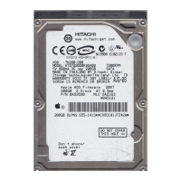
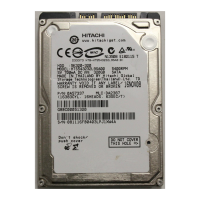
Overview of the Hitachi Travelstar 5K320 HDD and its SATA interface.
Introduces the Hitachi Travelstar 5K320 HDD and its SATA interface.
Lists and defines abbreviations used in the document.
Provides general warnings and precautions for handling the drive.
Details specific precautions for handling the hard disk drive.
Specifies the physical dimensions of the drive.
Describes the recording technology used on the drive.
Describes the components and technologies of the fixed disk subsystem.
Details the functions of the drive's control electronics.
Describes the technologies used in the head disk assembly.
Details physical and logical characteristics of the drive.
Lists formatted capacities for different drive models.
Presents key technical specifications and performance data.
Details the allocation of cylinders and sectors for data formatting.
Outlines key performance metrics of the drive.
Defines command overhead time and its measurement.
Covers seek times and latency.
Specifies typical and maximum average seek times for read/write.
Details the time taken for the drive to become ready after power-on.
Explains different operational states of the drive.
Provides timing for transitions between operating modes.
Discusses data integrity aspects, including power loss and write cache.
Explains potential data loss during power interruptions.
Describes the write cache function and data loss prevention.
Explains how drive errors are handled and reported.
Describes automatic reallocation of sectors with errors.
Explains the Error Correction Code (ECC) capabilities.
Details the environmental, electrical, and mechanical specifications.
Specifies operating and non-operating environmental conditions.
Details temperature and humidity limits for operation and storage.
Specifies limits for magnetic flux density to avoid data degradation.
Outlines requirements for handling conductive noise.
Lists voltage, ripple, and power consumption specifications.
Shows power consumption efficiency per capacity.
Covers data reliability, failure prediction, and usage conditions.
States the probability of data recovery and ECC implementation.
Mentions S.M.A.R.T. support for failure prediction.
Describes the load/unload mechanism and its life.
Explains the emergency unload process and its limitations.
Details the correct procedure for powering off the drive.
Details physical dimensions, weight, and mounting.
Lists the physical dimensions and weight of the drive models.
Shows diagrams of the drive's mounting hole positions.
Discusses operating axes and recommended mounting practices.
Specifies vibration and shock resistance levels.
Specifies vibration levels the drive can withstand during operation.
Details random vibration test levels and duration.
Specifies vibration levels the drive can withstand when not operating.
Lists shock test criteria for the drive during operation.
Details sound power level measurements.
Describes A-weighted sound power levels for idle and operating modes.
Describes the various labels affixed to the drive.
Details EMC requirements and certifications.
Confirms compliance with EC directive 89/336/EEC.
Covers safety approvals, compliance, and flammability.
States qualifications per UL60950-1:2003.
Confirms compliance with IEC 60950-1:2001.
Details cabling, connector, and signal definitions.
Specifies maximum cable length and pattern length.
Shows the physical pin location of the interface connector.
Lists pin assignments for interface signals.
Defines outbound differential signals for the SATA cable.
Shows timing diagrams for COMRESET, COMINIT, and COMWAKE.
Part 2 of the specification detailing interface aspects.
General information about the host interface.
Describes the host interface conforming to Serial ATA Rev 2.6.
Defines terms like Device, Host, and INTRQ.
Details deviations from the referenced SATA specifications.
Describes the physical interface aspects of the drive.
Details the host adapter registers and their purpose.
Maps ATA register names to specification names.
Describes the command register for sending commands to the device.
Details the bits and function of the Device Control Register.
Explains the Device Register for device and head numbers.
Describes the Error Register for status and diagnostic codes.
Details the LBA High Register contents.
Details the LBA Low Register contents.
Details the LBA Mid Register contents.
Describes the Sector Count Register for data transfer requests.
Covers device operation, resets, diagnostics, and power management.
Explains responses to Power-On, COMRESET, and Software Reset.
Describes initial register values after reset.
Discusses considerations for diagnostics and resets.
Explains the Execute Device Diagnostic command.
Covers load/unload and power-off sequences.
Details the load/unload mechanism by ATA commands.
Explains logical CHS and LBA addressing modes.
Describes the structure of logical CHS addressing.
Introduces power management features and commands.
Explains Sleep, Standby, Idle, and Active modes.
Details the ABLE-3 feature for power saving.
Describes the performance idle mode operation.
Explains the purpose and operation of S.M.A.R.T.
Defines attributes used for device status analysis.
Explains attribute thresholds for determining device condition.
Lists S.M.A.R.T. commands for accessing data.
Details the security features like device lock and passwords.
Describes device locked, unlocked, and frozen modes.
Explains device behavior after setting a user password.
Details actions when a user password is forgotten.
Describes the attempt limit for the SECURITY UNLOCK command.
Shows command responses in different security modes.
Describes the function for accessing protected areas.
Provides an example of protected area operation in LBA mode.
Explains commands related to max security settings.
Describes the method for accurate seek time measurement.
Explains the write cache function and its behavior.
Details the reassign function for preparing sectors.
Describes automatic reallocation of sectors due to errors.
Details settings preserved across software resets.
Lists settings preserved across COMRESET.
Explains support for Native Command Queuing.
Describes the S.M.A.R.T. Command Transport feature set.
Groups commands by protocols and defines basic protocol rules.
Lists commands that transfer data from the device to the host.
Lists commands that transfer data from the host to the device.
Lists commands that do not involve data transfer.
Lists commands for DMA data transfers.
Describes commands for first-parity DMA transfers.
Provides detailed descriptions of all supported commands.
Reports drive spin-up status and media availability.
Allows modification of device configuration settings.
Restores previously made device configuration settings.
Returns device capabilities and supported features.
Reduces the set of optional commands, modes, or feature sets.
Performs internal diagnostic tests and stores results in Error Register.
Completes writing data from the cache to disk.
Extends the Flush Cache command functionality.
Formats a single logical track on the device.
Initializes sectors, disables lock function, and erases user data.
Requests device configuration information from the host.
Causes the device to enter performance Idle mode.
Immediately enters performance Idle mode and can unload heads.
Sets sectors per track and heads per cylinder.
Transfers data from the device's sector buffer to the host.
Reads sectors using DMA and transfers data to the host.
Extended Read DMA command for sector data transfer.
Reads sectors using queued DMA and transfers data.
Returns specified log sector contents to the host.
Defines the structure of the General Purpose Log Directory.
Defines the format of SMART error log sectors.
Contains the total number of errors attributable to the device.
Defines the format of the Extended SMART self-test log.
Indicates the most recent self-test descriptor.
Defines the format of the Command Error data structure.
Obtains information about Phy level events.
Explains how Phy counters can be reset.
Reads one or more sectors and transfers data to host.
Extended Read Multiple command for sector data transfer.
Returns the native max LBA/CYL of HDD unaffected by Set Max Address.
Returns native max LBA of HDD unaffected by Set Max Address Ext.
Reads one or more sectors and transfers data to host.
Extended Read Sector command for data transfer.
Verifies one or more sectors; no data transferred to host.
Extended Read Verify Sector command; no data transfer.
Moves read/write heads to cylinder 0.
Disables security mode feature (device lock function).
Prepares the device for security erase and unlocking.
Initializes sectors, disables lock function, and erases user data.
Enters frozen mode, rejecting security feature updates.
Enables security mode and sets master or user password.
Unlocks the password and enters device unlock mode.
Initiates a seek to the designated track and head.
Senses temperature in the device.
Establishes parameters affecting certain features.
Overwrites max LBA/CYL of HDD for a range of capacities.
Overwrites max address of HDD in a range of capacity.
Enables Read/Write Multiple commands and sets block size.
Causes the device to enter Sleep Mode.
Provides access to S.M.A.R.T. attributes and thresholds.
Lists S.M.A.R.T. subcommands selectable via Features Register.
Returns device's Attribute Thresholds to the host.
Enables/disables automatic saving of updated Attribute Values.
Returns specified log sector contents to the host.
Writes 512 bytes data to the specified log sector.
Disables all S.M.A.R.T. capabilities and functions.
Communicates device reliability status to the host.
Defines the data structure for attribute values.
Identifies the version of the Attribute Value/Threshold data structure.
Defines the information for each Attribute entry.
Defines the current status of the device's off-line activities.
Provides the status of the self-test routine execution.
Defines the data structure for attribute thresholds.
Defines information for each Threshold entry in the Data Structure.
Defines the S.M.A.R.T. error log sector structure.
Defines the 512 bytes making up the Self-test log sector.
Defines parameters for self-test and progress monitoring.
Shows Status/Error Register values for specific error conditions.
Causes the device to enter Standby Mode immediately.
Immediately enters Standby mode without affecting auto power down timeout.
Transfers a sector of data from host to device sector buffer.
Transfers sectors using DMA and writes data to media.
Extended Write DMA command for sector data transfer.
Writes data to media before reporting status, even with caching.
Transfers sectors using queued DMA and writes data.
Writes specified number of data sectors to a specific log.
Transfers sectors from host and writes data to media.
Extended Write Multiple command for sector data transfer.
Writes data to media before status reporting, even with caching.
Transfers sectors from host and writes data to media.
Extended Write Sector command for data transfer.
Causes device to report uncorrectable error on subsequent reads.
Details the timing of various operations and states.