-15-
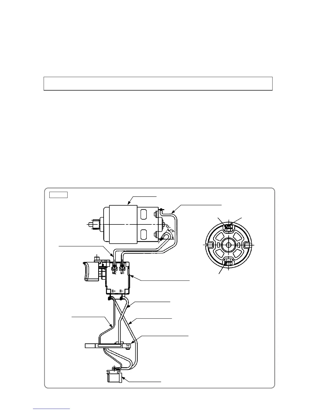
Terminal support
Controller Terminal Set [41]
Internal wire (white)
DC-Speed Control Switch [40]
Internal Wire (Red) [39]
Internal Wire (Black) [34]
Internal wire (brown)
Internal wire (red)
Motor [33]
Negative side
Positive side
Red marking
Fig. 3
7. Disassembly of the power supply unit
NOTE: Do not remove the heat sink secured to the DC-Speed Control Switch [40] with a screw.
Remove the two Machine Screw (W/Sp. Washer) M4 x 6 [28], and then separate the Motor Spacer [24]
from the Motor [33]. Use a soldering iron to disconnect the Internal Wire (Black) [34] and Internal Wire
(Red) [39] from the Motor [33], and then disconnect both from the DC-Speed Control Switch [40]. Next, use
the soldering iron to disconnect the DC-Speed Control Switch [40] and Controller Terminal Set [41] in the
same manner.
Reassembly can generally be performed by reversing the disassembly procedures. However, special
attention should be given to the following items.
1. Reassembly of the power supply unit
Perform wiring according to the wiring diagram. (See Fig. 3.) Pay attention to the connecting direction of the
internal wires and terminals.
• Solder the internal wire (white) coming from the top of the Controller Terminal Set [41] to the “B-“ terminal
of the DC-Speed Control Switch [40]. Then solder the internal wires (brown and red) coming from the top
of the Controller Terminal Set [41] to the “B+” terminal of the DC-Speed Control Switch [40] (Fig. 3).
• Solder the Internal Wire (Red) [39] to the “M1” terminal of the DC-Speed Control Switch [40] and
positive side terminal (with red marking) of the Motor [33] (Fig. 3).
• Solder the Internal Wire (Black) [34] to the “M2” terminal of the DC-Speed Control Switch [40] and
negative side terminal of the Motor [33] (Fig. 3).
Reassembl



 To Next Page