− 6 −
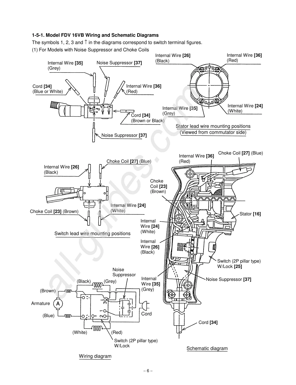
1-5-1. Model FDV 16VB Wiring and Schematic Diagrams
The symbols 1, 2, 3 and
↑
in the diagrams correspond to switch terminal figures.
(1) For Models with Noise Suppressor and Choke Coils
Internal Wire
[35]
(Grey)
Noise Suppressor
[37]
Cord
[34]
(Blue or White)
Internal Wire
[36]
(Red)
Internal Wire
[35]
(Grey)
Cord
[34]
(Brown or Black)
Noise Suppressor
[37]
Internal Wire
[26]
(Black)
Stator lead wire mounting positions
Internal Wire
[24]
(White)
(Viewed from commutator side)
Internal Wire
[36]
(Red)
Choke Coil
[27]
(Blue)
Internal Wire
[26]
(Black)
Choke Coil
[23]
(Brown)
Internal Wire
[24]
(White)
Switch lead wire mounting positions
Choke Coil
[27]
(Blue)
Internal Wire
[36]
(Red)
Choke
Coil
[23]
(Brown)
Stator
[16]
Internal
Wire
[24]
(White)
Internal
Wire
[26]
(Black)
Switch (2P pillar type)
W/Lock
[25]
Internal
Wire
[35]
(Grey)
Noise Suppressor
[37]
Cord
[34]
Schematic diagram
Noise
Suppressor
(Black) (Grey)
(Brown)
Armature
(Blue)
(White) (Red)
Switch (2P pillar type)
W/Lock
Wiring diagram
Cord