Number Item Description
1 POWER ON/OFF (main
switch)
Powers the storage system.
2 POWER, READY, WARNING,
and ALARM LEDs
Note: When System Option
Mode 1097 is set to ON,
the W
ARNING LED does not
blink, even if the following
failure service information
messages (SIM) are issued:
452xxx, 462xxx, 3077xx,
4100xx, and 410100.
3 Controllers Controller 1 (bottom) and
Controller 2 (top).
4 Backup module N/A
5 BACKUP LED Green: Power restoration in
progress following power
outage.
Fast blink green: Restoring.
Slow blink green: Restoring,
or sequential shutdown in
progress.
6 Cache ash memory N/A
7 ALM LED (for cache ash
memory)
Red: Cache ash memory
can be removed.
8 CTL ALM LED Red: Controller can be
r
emoved.
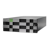
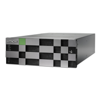
CBLH front panel LEDs (without bezel)
Chapter 2: Virtual Storage Platform G800 controller
Hitachi Virtual Storage Platform G800 Hardware Reference Guide 20
 Loading...