-5-
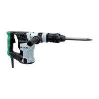
Valve Cover [38]
Seal Lock Hex. Socket
Hd. Bolt M4 x 8 [40]
Sectional view of Valve [37]
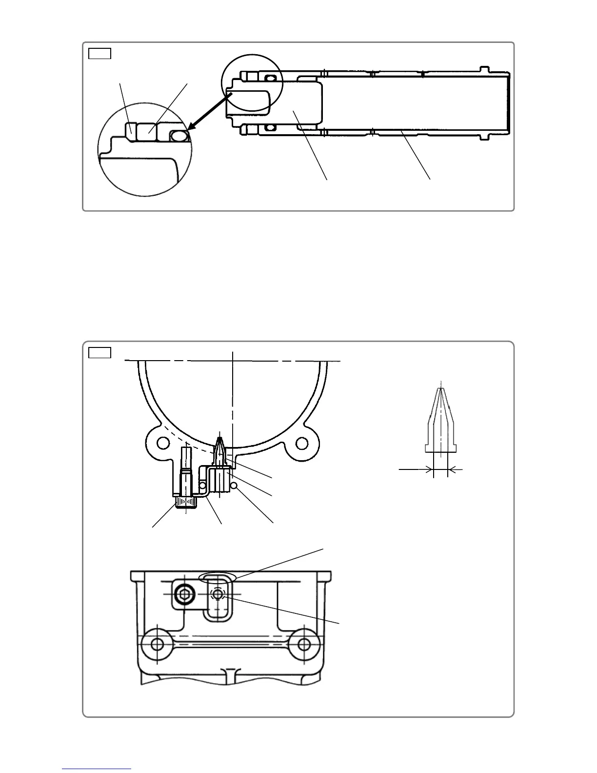
Cylinder [19]
Damper Washer [13]
(c) Valve [37], Valve Cover [38], and Felt [39]
Stick the Felt [39] on the Valve Cover [38] mating their top edges after degreasing the location on
the Valve Cover [38] where the felt is to be adhered. Fix the Felt [39] to the Valve Cover [38] with
the O-ring (S-10) [87]. Insert the Valve [37] into the Crank Case [44]. Fix the Valve Cover [38] in
place using the Seal Lock Hex. Socket Hd. Bolt M4 x 8 [40] by matching it to the seating surface of
the Crank Case [44]. Confirm that ĭ2.4 hole of the Valve [37] can be seen from the ĭ2 hole of the
Valve Cover [38] as shown in Fig. 6 below. Note that grease will leak if the Valve [37] is not
properly inserted. (Fig. 6)
The Felt [39] must not stick out
from the Valve Cover [38].
Felt [39]
ĭ2.4
ĭ2 hole of the Valve Cover [38]
Valve [37]
O-ring (S-10) [87]
Second Hammer [12]
Damper [14]
Fig. 5
Fig. 6


 To Next Page