EasyManua.ls Logo

Hitachi HA-7700 Service Manual

Hitachi HA-7700
30 pages
To Next Page IconTo Next Page
Page #1 background imageLoading...
Page #1 background image
www.mauritron.com
www.mauritron.com
.HITACHI
SERVICE
MANUAL
THE
QUALITY
OF
THIS
MANUAL
IS
THE
BEST
THAT
IS
AVAILABLE
SPECIFICATIONS
POWER
AMPLIFIER
SECTION
Power
output
65 watts
minimum
RMS
per
channel,
both
channels driven
into
8 ohms
load from
20-20,000
Hz
with
no more
than 0.02% total harmonic distortion.
Rated Power
Output
(both channels driven)
(8
ohms, 1 kHz, 0.01 %
THD):
70
watts+
70
watts
(4ohms.
1
kHz,0.01%
THD):
53watts+53watts
Power Band Width: 5
Hz-100
kHz
(0.03% THD)
Frequency Response
Direct Coupling:
Condenser Coupling:
Total Harmonic
Distortion
(20
Hz-20
kHz.
8 ohms
from
MAIN
IN)
at rated
output:
at 1
/2
rated
output:
Intermodulation
Distortion
(60 Hz : 7
kHz,
4 :
1)
at rated
output:
at 1
/2
rated
output:
Input
Sensinvity/lmpedance:
Input
Terminals:
Output
Terminals:
Signal-to-Noise Ratio
IHF. Short-Circuited,
DC-lOOkHz+0,-1
dB
4
Hz
(6
dB/Oct)
0.02%
0.005%
0.008%
0.003%
1 V (47 kohmsl
Direct Coupling/
Condenser Coupling
(Selected by
Rear
Panel
Switch)
A
or
B Speakers
A network, Rated Power: 115 dB
Damprng Factor
1 kHz. 8 ohms, 1
/2
rated
output:
60
Channel Separation
1 kHz. 8 ohms:
Speaker Impedance:
Phones
Impedance:
75 dB (4.7 kohms short)
4 ohms -
16
ohms
More than 4 ohms
English
Deutsch
Francrais
PREAMPLIFIER SECTION
Input
Sensitivity/Impedance
Phono 1, 2:
Tuner,
AUX:
Tape Play 1, 2:
Phono overload
(1
kHz.0.01%
THD)
Phono 1, 2:
Output
Level/Impedance
Pre-0ut:
Tape REC
out
1, 2:
Maximum
Output
Levels
(0.01% THD)
Pre-0ut:
Frequency
Response
Phono:
Tuner.
AUX:
Signal-to·Noise Ratio
(I
HF,
Short-Circuited
A
Network.
Rated Power)
Phono
1.
2:
Tuner,
AUX.
Tape Play
1.
2:
No. 160
For Service Manuals Contact
MAURITRON
TECHNICAL
SERVICES
8 Cherry Tree
Rd,
Chinnor
Oxon
OX94QY
Tel:-
01844-351694
Fax:-01844-352554
Email:-
enquiries@mauritron.co.m
MM 2.5
mV
(100 ohms, 22 kohms.
47 kohms, 100 kohms)
MC
250
µ.V
(100 ohms)
150
mV
(47 kohms)
150
mV
(47 kohms)
[Tape play 2
(DIN):
150
mV
(47 kohmsl
(Except
for
U.S.A. &
Canada)]
MM 300
mV
MC
30
mV
1 V (600 ohms)
150
mV
(600 ohms)
[Tape
REC
out
2
(DIN):
50
mV
(80 kohms)
(Except
for
U.S.A. &
Canada)]
More than 7 V-
(
MUTE:
OFF)
20
Hz-20
kHz.
±0.2 dB
10
Hz-100
kHz,
+O
-2.5
dB
MM 86 dB. MC 68 dB
lOOdB
100 dB
STEREO
AMPLIFIER
March
1979
Question and Answer IconNeed help?

Do you have a question about the Hitachi HA-7700 and is the answer not in the manual?

Hitachi HA-7700 Specifications

General IconGeneral
TypeStereo Integrated Amplifier
Power Output75 watts per channel into 8Ω (stereo)
Damping Factor60
Output150mV (line)
Speaker Load Impedance4Ω to 16Ω
Input Impedance50kΩ
Input Sensitivity150mV (line)

Summary

Technical Specifications

Power Amplifier Specifications

Details on output power, bandwidth, distortion, and performance metrics.

Preamplifier Specifications

Details on input sensitivity, overload, output levels, frequency response, and performance.

General Unit Specifications

Muting, dimensions, weight, power consumption, and requirements.

Key Features and Design

Low Distortion and High Power Design

Focus on low distortion, high power gain, and stable operation using MOS FETs.

DC Amplifier and Independent Power Supplies

DC amplifier for accurate transmission and independent power supplies for enhanced sound quality.

Advanced Preamplifier Performance

MC head amp, equalizer amp for improved S/N, RIAA deviation, and overload capability.

Protection and Selector Features

High-reliability protection circuitry and PHONO selector switch functionality.

Service and Adjustment Procedures

Service Precautions and Component Handling

Precautions for checking, repairing, and replacing components, including safety.

Amplifier Adjustment Procedures

Step-by-step instructions for adjusting idle current, input DC, and output DC.

Circuit Operation Checks

Procedures for checking MOS FET, ASO, and speaker protection circuit operations.

System Diagrams

Block and Circuit Diagrams

Overall system block diagram and primary circuit diagram for specific regions.

Printed Wiring Board Layouts

Main Amplifier PWB Layout

Printed wiring board layout for the main amplifier section.

Pre-Amplifier and Power Supply PWB Layouts

Printed wiring board layouts for pre-amplifier and power supply sections.

Front Panel Controls

Front Panel Overview and Identification

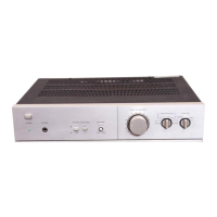
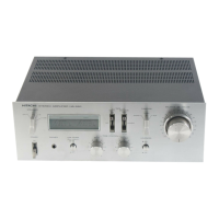
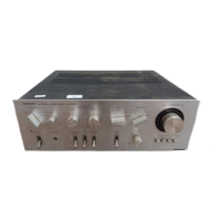
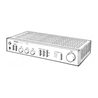
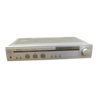
Identification of all controls, switches, and indicators on the front panel.

Replacement Parts Lists

Capacitors and Resistors

Lists of replacement capacitors and resistors for various unit sections.

FETS, ICs, Transistors, Diodes

Lists of replacement FETS, ICs, transistors, and diodes for unit sections.

Coils, Switches, and Connectors

Lists of replacement coils, switches, connectors, and other miscellaneous parts.

Rear Panel Connections

Input/Output and Speaker Terminals

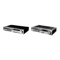
Identification of rear panel input, output, and speaker terminals.

Tape, Tuner, Phono, and AUX Connections

Rear panel connections for tape decks, tuner, phono, and auxiliary inputs.

Power and Voltage Selectors

Rear panel power cord, AC outlets, and voltage selector information.

Related product manuals