– 37 –
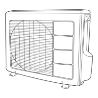
3. Buzzer Circuit
HIC
(AX-3Q)
Buzzer
Buzzer
4kHz
12V
R801
21
Fig. 3-1
When the buzzer is to be activated, buzzer output pin
q
of the HIC alternates between ON and OFF repeatedly at 4kHz.
And a 4kHz voltage is applied to the buzzer and the diaphragm of the buzzer vibrates to output 4kHz sound.
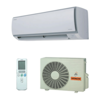
4. Initial Setting (IC401)
Initial setting of microcomputer, wind direction control and, etc.
1
2
3
4
8
59
58
7
6
5
IC401
C401
R402
R401
SCL
EXTERNAL
ROM
MICON
SDA
R406
R405
0V
0V 0V
5V
5V
5V
}
Fig. 4-1
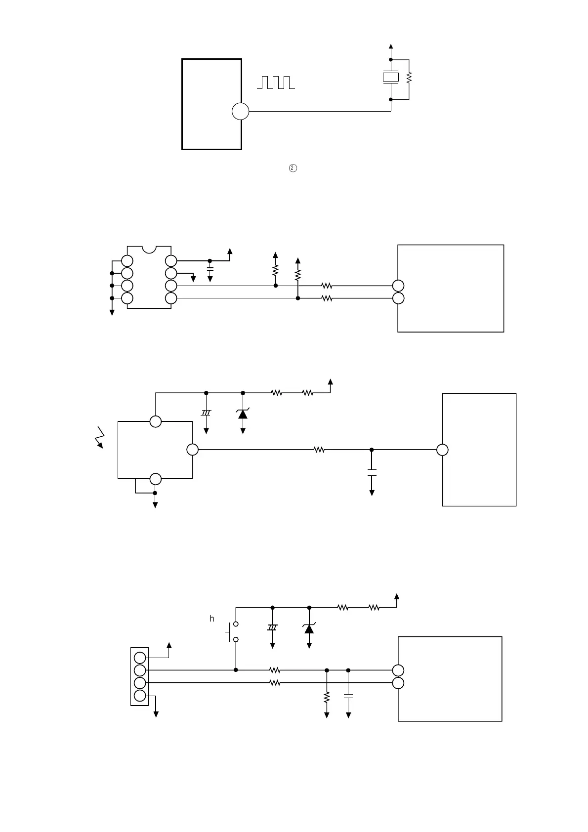
5. Receive circuit
18
C702
0V
0V
0V
0V
12V
R710
ZD701
R709
R705
C701
INFRARED
RECEIVING
UNIT
MICON
+
–
● The temporary switch is used when the wireless remote controller is lost or troubled.
● Last operation mode and last set temperature are selected or, once the power switch is turned off, an automatic
operation is selected.
0V
23
31
3
2
1
4
R610
0V
0V
5V
C1
C2
M1
M2
0V
12V
R710
ZD701
R709
HA INPUT
HA OUTPUT
R609
C601
R611
C701
(SW1)
CN7
MICON
+
–
0V
6. Temporary Switch Circuit
Infrared signals from the wireless remote controller are received by the light receiving unit and output after being amplified
and shaped.
Temporary Switch
 Loading...