EasyManua.ls Logo

Hitachi RAC-50WPB User Manual

Hitachi RAC-50WPB
148 pages
To Next Page IconTo Next Page
Page #1 background imageLoading...
Page #1 background image
SPECIFICATIONS AND PARTS ARE SUBJECT TO CHANGE FOR IMPROVEMENT
ROOM AIR CONDITIONER
INDOOR UNIT + OUTDOOR UNIT
SERVICE MANUAL
REFER TO THE FOUNDATION MANUAL
TECHNICAL INFORMATION
FOR SERVICE PERSONNEL ONLY
SPECIFICATIONS
CONTENTS
SPECIFICATIONS ------------------------------------------------------------------- 6
HOW TO USE ----------------------------------------------------------------------10
CONSTRUCTION AND DIMENSIONAL DIAGRAM --------------------- 43
MAIN PARTS COMPONENT --------------------------------------------------- 48
WIRING DIAGRAM ---------------------------------------------------------------- 50
CIRCUIT DIAGRAM --------------------------------------------------------------- 52
After installation
BLOCK DIAGRAM ----------------------------------------------------------------- 55
BASIC MODE ----------------------------------------------------------------------- 56
REFRIGERATING CYCLE DIAGRAM --------------------------------------- 67
DESCRIPTION OF MAIN CIRCUIT OPERATION ----------------------- 73
SERVICE CALL Q & A ---------------------------------------------------------- 98
TROUBLE SHOOTING -----------------------------------------------------------102
PARTS LIST AND DIAGRAM --------------------------------------------------1
HHAW
RAK-18PPB/RAC-18WPB
RAK-25PPB/RAC-25WPB
RAK-35PPB/RAC-35WPB
RAK-50PPB/RAC-50WPB
INDOOR UNITOUTDOOR UNIT
INDOOR UNIT
OUTDOOR UNIT
INDOOR UNIT OUTDOOR UNIT INDOOR UNIT OUTDOOR UNIT
INDOOR UNIT OUTDOOR UNIT
RAK-18P
RAC-18W
RAK-25P RAC-25W RAK-35P RAC-35W
RAK-50P RAC-50W
(KW)
(B.T.U./h)
(KW)
(B.T.U./h)
W
780 660(+60) 780 660(+60) 900 750(+65)
900 792(+91)
H
280 530 280 530 295 548
295 600
D
218 278(+35) 218 278(+35) 230
288(+27.5)
230 299(+47)
MODEL
POWER SOURCE
TOTAL INPUT (W
TOTAL AMPERES (A)
CAPACITY
COOLING
HEATING
TOTAL INPUT (W
TOTAL AMPERES (A)
CAPACITY
1,090 (250
1,460)
DIMENSIONS
(mm)
1,560 (500
2,100)
3.12-2.97
2.00 (0.90
2.50)
8,530 (3,070
10,580)
580 (250
970)
2.50 (0.90
27.57.5 27.57.5 3410
10
3.20)
3.49-3.34
11,600 (3,070
15,010)
880 (250
1,250)
NET WEIGHT (Kg)
TYPE
DC INVERTER
1 PHASE,50HZ,220-230V
1 PHASE,50HZ,220-230V 1 PHASE,50HZ,220-230V
550 (
700 (250
) 010 , 1
1,290)
4.56-4.36
3.40 (0.90
4.40)
11,600 (3,070
15,010)
4.87-4.66
1,100 (250
1,700)
5.51-5.27
14,330 (3,070
17,060)
3.75-3.59
2.50 (0.90
3.10)
8,530 (3,070
10,580)
7.30-6.98
3.50 (0.90
4.00)
5.00 (1.90
5.20)
11,940 (3,070
13,650)
17,060 (6,480
17,740)
20,470 (7,510
24,910)
7.93-7.59
1,660 (500
2,750)
4.20 (0.90
5.00)
6.00 (2.20
7.30)
25
0
Hitachi Household Appliances(Wuhu) Co., Ltd.
PB
PB
PB PB PB PB
PB PB
RAC-18WPB
RAC-25WPB
RAK-18PPB
RAK-25PPB
RAC-50WPB
RAC-35WPB
1 PHASE,50HZ,220-230V
RAK-35PPB
RAK-50PPB
NO.0080E-3
38
40
PROCEDURE FOR DISASSEMBLY AND REASSEMBLY-------------70
RAR-5E2
RAR-5E1

Table of Contents

Other manuals for Hitachi RAC-50WPB

Question and Answer IconNeed help?

Do you have a question about the Hitachi RAC-50WPB and is the answer not in the manual?

Hitachi RAC-50WPB Specifications

General IconGeneral
BrandHitachi
ModelRAC-50WPB
CategoryAir Conditioner
LanguageEnglish

Summary

SAFETY DURING REPAIR WORK

WORKING STANDARDS FOR PREVENTING BREAKAGE OF SEMICONDUCTORS

Scope

Defines the applicability of the standards for handling semiconductors.

Object parts

Lists the components covered by the standards, including microcomputers and ICs.

Items to be observed in handling

Details the procedures for safe handling of semiconductor parts.

SPECIFICATIONS

PREPARATION BEFORE OPERATION

To install the batteries

Instructions for inserting batteries into the remote control.

To fix the remote controller holder to the wall

Steps for mounting the remote control holder securely.

NAMES AND FUNCTIONS OF REMOTE CONTROLLER

To set calendar and clock

Procedure for setting the unit's current time and date.

Precautions for Use

Guidelines for proper use and placement of the remote controller.

AUTOMATIC OPERATION

Describes how the unit automatically selects operation modes.

HEATING OPERATION

DEHUMIDIFYING OPERATION

COOLING OPERATION

FAN OPERATION

POWERFUL OPERATION

AUTO SWING OPERATION

SILENT OPERATION

ECO OPERATION

LEAVE HOME(LH) OPERATION

CLEAN (ONE TOUCH CLEAN) OPERATION

ONCE TIMER (ON/OFF TIMER) OPERATION

ECO SLEEP TIMER OPERATION

WEEKLY TIMER OPERATION

INFO FUNCTION

OPERATION MODE LOCK

Remote Controller Manual

PREPARATION BEFORE OPERATION

Initial setup procedures for the remote controller.

To set calendar and clock

Procedure for setting the unit's current time and date.

NAMES AND FUNCTIONS OF REMOTE CONTROLLER

Details remote controller buttons, features, and operations.

HEATING OPERATION

DEHUMIDIFYING OPERATION

COOLING OPERATION

FAN OPERATION

POWERFUL OPERATION

SILENT OPERATION

ECO OPERATION

LEAVE HOME(LH) OPERATION

CLEAN (ONE TOUCH CLEAN) OPERATION

ONCE TIMER (ON/OFF TIMER) OPERATION

ECO SLEEP TIMER OPERATION

WEEKLY TIMER OPERATION

INFO FUNCTION

OPERATION MODE LOCK

SAFETY PRECAUTION

NAMES AND FUNCTIONS OF EACH PART

INDOOR UNIT

Details the components and parts of the indoor unit.

OUTDOOR UNIT

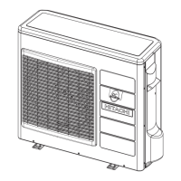
Details the components and parts of the outdoor unit.

MAINTENANCE

1. AIR FILTER

Instructions for cleaning the air filter to maintain performance.

2. CLEANING OF FRONT PANEL

Steps for cleaning the unit's front panel.

3. MAINTENANCE AT BEGINNING OF LONG OFF PERIOD

Procedures for maintaining the unit during long periods of non-operation.

INFORMATION

CAPABILITIES

Describes the unit's heating, cooling, and dehumidifying features.

REGULAR INSPECTION

Routine checks for unit health and safety.

AFTER SALES SERVICE AND WARRANTY

Guidance for service, warranty claims, and contact information.

CONSTRUCTION AND DIMENSIONAL DIAGRAM

INDOOR UNIT

Diagrams and dimensions for indoor units.

OUTDOOR UNIT

Diagrams and dimensions for outdoor units.

MAIN PARTS COMPONENT

Thermostat Specifications

Technical data for thermostat components.

FAN MOTOR

Details on fan motor specifications and connection.

MAIN ELECTRIC COMPONENTS FOR OUTDOOR UNIT

Key electrical parts for outdoor units, including reactors.

COMPRESSOR MOTOR

Compressor Motor Specifications

Technical data for the compressor motor and its resistance values.

WIRING DIAGRAM

WIRING DIAGRAM

Electrical connection schematics for various models.

CIRCUIT DIAGRAM

BLOCK DIAGRAM

BASIC MODE

REFRIGERATING CYCLE DIAGRAM

COOLING CYCLE

Diagram of refrigerant flow during cooling operation.

HEATING CYCLE

Diagram of refrigerant flow during heating operation.

Procedure for Disassembly and Reassembly

INDOOR UNIT RAK-18/25/35/50PPB

Steps to disassemble indoor unit components.

1. Electrical Parts

Procedures for removing electrical parts from the outdoor unit.

4. Tangential air flow fan and fan motor

Steps for removing the tangential fan and fan motor.

DESCRIPTION OF MAIN CIRCUIT OPERATION

1. Control power circuit

Explanation of the control power circuit's function.

TROUBLE SHOOTING

Inspection instructions

Guidelines for inspecting the unit for potential issues.

DISCHARGE, PROCEDURE AND POWER SHUT OFF METHOD FOR POWER CIRCUIT

STRUCTURE OF AN INDOOR UNIT ELECTRIC PARTS

Removing electrical parts

Steps to remove electrical components from the indoor unit.

Removing control P.W.B.

Procedure to remove the control circuit board.

Removing the indicating P.W.B.

Procedure to remove the indicator circuit board.

Troubleshooting support

1 Self-diagnosis display [Display on the indoor unit side]

Interpreting indoor unit self-diagnosis indicators.

[Display on the outdoor unit side]

Interpreting outdoor unit self-diagnosis indicators.

2 Self-diagnosis memory

How to access and manage stored failure data.

SELF-DIAGNOSIS LIGHTING MODE

Forced cooling operation

Diagnosis and troubleshooting of indoor electric parts, outdoor electric parts and refrigerating cycle

Checking the indoor unit electrical parts

Introduction

Overview of the process for checking indoor unit electrical parts.

Initiating troubleshooting

Initial steps for diagnosing issues with indoor unit electrical parts.

1. Failure phenomenon: The power will not become turned on.

2.Failure phenomenon: The product will not receive a remote control signal.

Cautions

Important warnings regarding remote signal reception issues.

Diagnosis flow Initiating troubleshooting

Steps to diagnose remote control signal reception problems.

How to identify sources of jamming in the reception of remote control signals

[ Situation ]

Potential causes of signal interference with remote control.

[ Estimating sources of jamming ]

Identifying installation factors that may cause jamming.

Checking points

Specific checks to identify sources of interference.

Actions proposed

Recommended solutions for addressing signal interference.

Effects of lighting equipment (fluorescent lamps)

How lighting equipment affects remote signal reception.

3. Failure phenomenon: The compressor will not run.

[ Situation ]

Condition when the compressor fails to run.

[ Estimated failure locations ]

Possible causes for compressor failure.

[ Diagnosis flow ] Initiating troubleshooting

Diagnostic steps for compressor issues.

4. Failure phenomenon: The fan motor will not stop.

Estimated failure locations

Potential causes for the fan motor not stopping.

Diagnosis flow Initiating troubleshooting

Diagnostic steps for fan motor issues.

5. Timer lamp blinking: blinking once

6. Timer lamp blinking: blinking twice

7. Timer lamp blinking: blinking three times

[Cautions]

Warnings related to terminal board replacement.

[Diagnosis flow] Initiating troubleshooting

Diagnostic steps for timer lamp blinking three times.

8. Timer lamp blinking: blinking four times

9. Timer lamp blinking: blinking 9 times

[Situation]

Condition indicating 9 timer lamp blinks.

[Estimated failure location]

Possible causes for 9 timer lamp blinks.

[Cautions]

Warnings about failure detection initiation.

[Diagnosis flow] Initiating troubleshooting

Diagnostic steps for 9 timer lamp blinks.

10. Timer lamp blinking: blinking 10 times

[Situation]

Condition indicating 10 timer lamp blinks.

[Estimated failure locations]

Possible causes for 10 timer lamp blinks.

[Diagnosis flow] Initiating troubleshooting

Diagnostic steps for 10 timer lamp blinks.

11. Timer lamp blinking: blinking 12 times

[Estimated failure locations]

Possible causes for 12 timer lamp blinks.

[Cautions]

Warnings about F cable connection.

[Diagnosis flow] Initiating troubleshooting

Diagnostic steps for 12 timer lamp blinks.

1. Timer lamp blinking: blinking 13 times

[Situation]

Condition indicating 13 timer lamp blinks.

[Estimated failure location]

Possible causes for 13 timer lamp blinks.

[Diagnosis flow]

Diagnostic steps for 13 timer lamp blinks.

Checking the electrical parts of the outdoor unit

HOW TO CHANGE THE SHIFT VALUE SETTING TEMPERATURE

SETTING THE PREVENTION OF MUTUAL INTERFERENCE FOR REMOTE CONTROLLER

OPERATION MODE LOCK SETTING

DISPLAY OPERATION MODE SETTING

CHECKING THE REFRIGERATING CYCLE

(JUDGING BETWEEN GAS LEAKAGE AND COMPRESSOR DEFECTIVE)

Method to diagnose gas leaks or compressor issues.

How to run the product with the outdoor unit test switch

HOW TO OPERATE THE OUTDOOR UNIT INDEPENDENTLY

PARTS LIST AND DIAGRAM

INDOOR UNIT MODEL: RAK-18/25PPB

Parts breakdown and list for RAK-18/25PPB indoor units.

INDOOR UNIT

Parts list for RAK-35/50PPB indoor units.

OUTDOOR UNIT MODEL RAC-18/25WPB

Parts breakdown and list for RAC-18/25WPB outdoor units.

OUTDOOR UNIT

Parts list for RAC-35/50WPB outdoor units.

Related product manuals