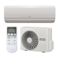
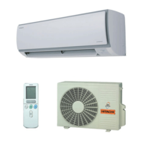
This document is an installation and operation manual for Hitachi air conditioning units, specifically models RAK-AJ10PCASV/RAC-AJ10PCASV, RAK-AJ13PCASV/RAC-AJ13PCASV, RAK-AJ18PCASV/RAC-AJ18PCASV, and RAK-AJ24PCASV/RAC-AJ24PCASV. It covers remote controller instructions, safety guidelines, installation procedures, maintenance, and troubleshooting.
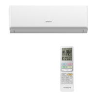
Remote Controller
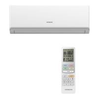
The remote controller transmits signals to the air conditioning system. It features several buttons for controlling various functions:
- ON/OFF BUTTON (1): Starts or stops the appliance.
- MODE BUTTON (2): Selects the operation mode (Cooling, Dry, Fan Only, Heating).
- FAN BUTTON (3): Selects fan speed in sequence: auto, high, medium, or low.
- ROOM TEMPERATURE SETTING BUTTONS (4, 5): Adjusts the room temperature and sets the timer.
- TURBO BUTTON (6): Initiates or stops fast cooling (operates at high fan speed with a 16°C set temperature automatically).
- SWING BUTTON (7): Controls vertical adjustment of the louver for desired up/down airflow.
- SLEEP BUTTON (8): Activates or cancels Sleep Mode.
- LIGHT BUTTON (9): Turns off all displays on the indoor unit.
- CLOCK BUTTON (10): Sets the current time.
- TIMER ON/OFF BUTTON (11, 12): Sets or cancels timer operations.
- ECO BUTTON (13): Activates or cancels Economy Mode.
- SWING BUTTON (14): Controls horizontal adjustment of the louver for desired left/right airflow.
- MUTE BUTTON (15): Activates or deactivates the MUTE function for low noise operation.
- IFEEL BUTTON (17): Activates or deactivates IFEEL mode, which uses a temperature sensor in the remote controller to adjust the unit's temperature for maximum comfort.
- CLEAN BUTTON (16): Initiates the CLEAN function.
- LOCK (11+12): Pressing TIMER ON and TIMER OFF buttons together for 3 seconds locks or unlocks the remote controller.
LCD Indication Symbols:
The LCD displays various symbols indicating the current status:
- Cooling, Dry, Fan only, Heating indicators
- Auto fan speed, Higher/High, Medium, Low fan speed, Lower fan speed
- Smart indicator, Sleep indicator, Economy indicator, Ifeel, Lock, Mute indicator
- Signal transmit, Display set timer, Display current time, Display temperature
- Nanoe indicator, Turbo indicator
- Airflow left/right and up/down indicators
Remote Controller Battery Installation:
To insert batteries, remove the battery cover by sliding it back. Insert two LR03 AAA (1.5V) batteries, ensuring correct polarity. Replace batteries when the display becomes dim. The remote controller can be stored on a wall with an optional holder.
Operation Modes
Selecting Mode:
Pressing the "MODE" button cycles through COOLING, DRY, FAN ONLY, and AUTO modes. Heating mode is not available for cooling-only air conditioners.
FAN Mode:
Pressing the "FAN" button cycles through fan speeds: Auto, Higher, High, Medium, Low, and Lower. In "FAN ONLY" mode, fan speed is ineffective if set to "Auto."
Setting Temperature:
Use the "+" button to increase temperature by 1°C and the "-" button to decrease it by 1°C. Holding the button for 2 seconds adjusts by 10 minutes, and for a longer time, by 1 hour. The temperature range for heating and cooling is 16°C to 30°C.
Turning On:
Pressing the ON/OFF button turns on the appliance, and the RUN indicator on the indoor unit lights up.
Airflow Direction Control:
- Vertical Airflow (Horizontal airflow): Automatically adjusts to a certain angle. The direction can be manually adjusted using the SWING button on the remote controller.
- Horizontal Airflow: Automatically adjusts. The direction can be manually adjusted using the SWING button.
- Desired Direction Airflow: Press the SWING button to set the louvers to a suitable angle.
CLOCK Button:
Adjust the real time using the "+" and "-" buttons, then press CLOCK again to set.
Timer Mode:
- Setting TIMER ON: Press TIMER ON, "ON 12:00" flashes. Use "+" or "-" to select the desired time. Press TIMER ON again to confirm. The TIMER indicator on the indoor unit lights up. If no action for 10 seconds, the remote controller exits TIMER ON mode.
- Canceling TIMER ON: Press TIMER ON again.
SLEEP Mode:
Available in COOLING, HEATING, or DRYING modes.
- Appliance stops automatically after 8 hours.
- Fan speed is automatically set to low.
- In cooling mode, set temperature rises by 1°C per hour for 1 hour, then remains steady. If room temperature is 26°C or above, set temperature does not change.
- In heating mode, set temperature decreases by 3°C per 3 hours, then remains steady.
- For G1Q series: In cooling, set temperature rises by 2°C per 2 hours. In heating, set temperature decreases by 2°C per 2 hours.
- Can be canceled by pressing TURBO, ON/OFF, FAN, MODE, ECO, or SLEEP buttons.
TURBO Mode:
Starts or stops fast cooling.
- In cooling, fan only, or dry mode: Sets high fan speed and temperature to 16°C.
- In heating mode: Sets auto fan speed and temperature to 30°C.
- Can be canceled by pressing TURBO, MODE, FAN, ON/OFF, SLEEP, or MUTE buttons.
LOCK Function:
Press TIMER ON and TIMER OFF buttons together for 3 seconds to activate/deactivate. The lock icon appears/disappears on the LCD.
MUTE Mode:
Operates with low noise. SLEEP mode can be started simultaneously. Available in COOLING, HEATING, and FAN ONLY modes. Canceled by pressing MODE, FAN SPEED, SMART, or SUPER.
ECO Mode:
Provides energy-saving performance. ECONOMY button is ineffective in SMART and SUPER modes. Canceled by pressing ON/OFF, MODE, TEMP ±, FAN SPEED, SLEEP, QUIET, or ECONOMY.
IFEEL Function:
Activates the temperature sensor in the remote controller to sense surrounding temperature and transmit signals to the unit, adjusting for maximum comfort. Place the remote controller where the indoor unit can easily receive signals. Cancel IFEEL mode to save energy when stopping the air conditioner.
CLEAN Function:
When the air conditioner is in standby and the remote controller is in Cooling or Dry mode, press CLEAN to start Clean mode. The indicator appears on the LCD. Ineffective in TURBO mode. Canceled by pressing ON/OFF or MODE. After the clean process, the unit returns to preset Cooling or Dry, and the indicator displays for about 10 minutes.
Safety Instructions
The manual emphasizes several safety precautions for installation, operation, and maintenance:
- Read the manual thoroughly before installation and use.
- Ensure proper grounding and electrical connections.
- Use appropriate circuit breakers and disconnecting devices.
- Do not modify the appliance or use non-specified parts.
- Keep flammable materials away from the unit.
- Ensure proper ventilation for the outdoor unit.
- Do not obstruct air inlets or outlets.
- Use appropriate personal protective equipment during installation and servicing.
- Be cautious with refrigerants (R32) due to flammability.
- Ensure proper handling and storage of refrigerants.
- Regularly check for leaks and maintain the system.
- Decommissioning procedures must be followed carefully, including refrigerant recovery and proper labeling.
Technical Specifications (Refrigerant and Pipe Lengths):
- Max. allowed pipe length without additional refrigerant: 5 meters for 5K-36K models.
- Limit of pipe length: 15 meters for 5K-36K models.
- Limit of Elevation Difference H: 5 meters for 5K-36K models.
- Required amount of additional refrigerant: 20 g/m for 5K-18K, 30 g/m for 21K-25K, 40 g/m for 28K-36K.
Cable Specifications (Inverter Appliance):
- 5K~13K: Power cord 0.75~1.5mm²X3 (H07RN-F/H05VV-F/IS:694), connecting cord 0.75mm²X4 (H07RN-F/H05RN-F/IS:9968).
- 14K~18K: Power cord 1.5mm²X3 (H07RN-F/H05VV-F/IS:694), connecting cord 1.5/2.5mm²X4 (H07RN-F/H05RN-F/IS:9968).
- 21K~36K: Power cord 2.5mm²X3 (H07RN-F/H05VV-F/IS:694), connecting cord 0.75~2.5mm²X4/X5 (H05RN-F/H07RN-F/IS:9968).
- For 14K~18K models under Tropical (T3) Climate condition:** Power cord and connecting cord are 2.5mm²×4.
Cable Specifications (ON-OFF Appliance):
- 5K~13K: Power cord 0.75~1.5mm²X3 (H05VV-F), connecting cord 0.75~1.5mm²X3 (H07RN-F/H05RN-F).
- 14K~24K: Power cord 1.5~2.5mm²X3 (H05VV-F), connecting cord 1.5~2.5mm²X3 (H07RN-F/H05RN-F).
- 18K-30K: Power cord 1.5~2.5mm²X3 (H05VV-F), connecting cord 1.5~2.5mm²X4 (H07RN-F/H05RN-F).
- 24K-36K: Power cord 2.5~4.0mm²X3 (H07RN-F), connecting cord 0.75~1.5mm²X4/X5 (H07RN-F/H05RN-F).
Installation Instructions
Installation Diagram:
Provides recommended clearances from walls and ceiling for both indoor and outdoor units to ensure proper airflow and maintenance access.
- Indoor Unit: Distance from ceiling should be over 200mm. Distance from wall should be over 50mm.
- Outdoor Unit: Distance from obstacle should be over 300mm. Air intake distance from the wall should be over 250mm. Air outlet distance from the wall should be over 500mm.
Location Selection:
- Indoor Unit: Choose a location with no obstacles near the air outlet, easy pipe arrangement, sufficient space from ceiling and walls, easy filter removal, away from electronics and heat sources, and on a strong wall.
- Outdoor Unit: Select a well-ventilated location, away from flammable gas, greasy dirt, vulcanization gas, muddy water, direct sunlight, and heat sources. Ensure a fixed base to prevent vibration.
Indoor Unit Installation:
- Mounting Plate: Decide location, ensure horizontal level, drill 32mm deep holes, insert plastic plugs, fix with tapping screws, and drill a pipe hole.
- Pipe Hole: Drill a 50mm hole, tilting downward, and install a sleeve.
- Pipe Installation: Pass pipes and cables through the wall hole. Connect pipes and drain hose, then wrap with thermal insulation.
Pipe Joints Thermal Insulation:
Wrap pipe joints with thermal insulation materials and then with vinyl tape.
Pipes Thermal Insulation:
Place the drain hose under the pipes. Use polythene foam insulation over 6mm thickness. Ensure the drain pipe points downward for easy flow and is not twisted or immersed. Insulate extension drain hoses.
Piping Connection:
- Before unscrewing sealing caps, press the small cap with a finger until exhaust noise stops.
- Connect indoor unit pipes with two wrenches, paying attention to torque specifications to prevent deformation.
- Pre-tighten with fingers, then use wrenches.
Connecting the Cable:
- Indoor Unit: Connect power cord wires to terminals on the control board. For some models, cabinet removal may be necessary.
- Outdoor Unit: Remove access door, connect wires to terminals, secure power cord with cable clamp, and reinstall access door. Use a circuit breaker for 24K models.
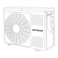
Outdoor Unit Installation:
- Drain Port and Drain Hose (heat-pump models): Install drain port and rubber washer to the chassis, then connect a drain hose to direct condensate water.
- Fix Outdoor Unit: Securely fix with bolts and nuts on a flat, strong floor or wall/roof with proper support.
- Piping Connection: Remove valve caps, connect pipes to 2-way and 3-way valves with specified torque.
- Cable Connection: Refer to previous page for wiring.
Air Purging:
After connecting units, release air and moisture from the refrigerant cycle using a vacuum pump to prevent compressor malfunction. Do not discharge refrigerant into the air.
Maintenance
Front Panel Maintenance:
- Cut off power supply.
- Grasp position "a" and pull outward to remove the front panel.
- Wipe with a soft and dry cloth. For heavy dirt, use a cloth dampened with warm water.
- Never use volatile substances like gasoline or polishing powder.
- Never sprinkle water onto the indoor unit.
- Reinstall and shut the front panel.
Air Filter Maintenance:
- Stop the appliance, cut off power supply.
- Open the front panel.
- Press the handle of the filter gently from the back.
- Grasp the handle and slide out the filter.
- Clean and reinstall the air filter. Clean with a vacuum cleaner or wash with water. Dry in shade.
- Close the front panel again.
- Clean air filter every two weeks.
- It is necessary to clean the air filter after using it for about 100 hours.
Protection
Operating Condition (Inverter Appliance):
- Temperature Range:
- Cooling: Indoor 18-32°C, Outdoor 18-43°C.
- Heating: Indoor 0-27°C, Outdoor -15-24°C.
- Drying: Indoor 10-32°C, Outdoor 10-43°C.
- Optimal performance is achieved within these operating temperatures.
- For some models, cooling at -15°C outdoor ambient via unique design.
- For some models, heating at -20°C outdoor ambient.
- If relative humidity is above 80%, dew may drip from the outlet.
Operating Condition (ON-OFF Appliance):
- Temperature Range:
- Cooling: Outdoor 18-43°C, Room temperature is below 21°C.
- Heating: Outdoor 18-24°C, Room temperature is over 27°C.
- Drying: Room temperature is below 18°C.
- For tropical (T3) climate, normal operating conditions are 18-55°C.
- If relative humidity is above 80%, dew may drip from the outlet.
Noise Pollution:
- Install the air conditioner at a place that can bear its weight.
- Install the outdoor unit at a place where the air discharge and the operation noise would not annoy neighbors.
- Do not place any obstacles in front of the air outlet of the outdoor unit.
Features of Protector:
- Restart Delay: 3 minutes after operation stops or mode change. 20 seconds after connecting to power supply.
- Timer Reset: If operation stops, press ON/OFF to restart, timer must be reset.
Features of HEATING Mode:
- Preheat: Airflow from indoor unit discharged 2-5 minutes after heating operation starts.
- Defrost: Appliance automatically defrosts (de-ices) to raise efficiency. Lasts 2-10 minutes. Fans stop during defrosting. Returns to heating mode automatically after defrosting. Not available for cooling-only models.
Troubleshooting
This section lists common issues that may not be malfunctions.
- Does not run:
- Protector trip or fuse blown.
- Wait 3 minutes for protector device to reset.
- Remote controller batteries exhausted.
- Plug not properly plugged.
- No cooling or heating air:
- Air filter dirty.
- Intakes/outlets blocked.
- Temperature not set properly.
- Ineffective control: Strong interference (static electricity, voltage abnormality) may cause abnormal operation. Disconnect power for 2-3 seconds.
- Does not operate immediately: Changing mode delays operation by 3 minutes.
- Peculiar odor: Odor from furniture, cigarettes, etc., sucked in and blown out by the unit.
- Sound of flowing water: Caused by refrigerant flow, not a malfunction. Defrosting sound in heating mode.
- Cracking sound: Generated by expansion/contraction of front panel due to temperature change.
- Spray mist from outlet: Appears when room becomes very cold during COOLING or DRY.
- Compressor indicator (red) lights constantly, indoor fan stops: Unit shifting to defrost from heating mode. Lights off within 10 minutes, returns to heating mode.
Display Introduction (LCD Symbols):
- Temperature indicator (88): Displays set temperature. "FC" after 200 hours indicates filter cleaning reminder.
- Running indicator: Lights up when AC is running, flashes during defrosting.
- Timer indicator: Lights up during set time.
- Sleep indicator: Lights up in sleep mode.
- Compressor indicator: Lights up when compressor is on.
- Mode indicator: Heating (orange), others (white).
- Fan speed indicator.
- Signal Receptor.
- Smart WIFI indicator: Lights up during WIFI is on.
- NANOE indicator: Lights up in NANOE mode.
- FAN ONLY mode indicator: Lights up in FAN ONLY mode.
- Airflow Follow You/Airflow Avoid You indicator.
- Humidity indicator: Lights up in humidity mode.
- Artificial Intelligence Smart Running Indicator: Lights up in AI mode.
Emergency Button:
A button on the indoor unit allows the AC to run or stop in an emergency. The symbol may differ by model.