Do you have a question about the Hitachi RAC-25WXE and is the answer not in the manual?
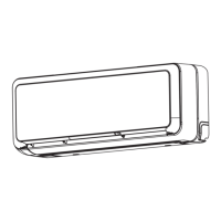
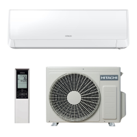
Detailed specifications for RAK-25RXE, RAK-35RXE, and RAK-50RXE indoor units.
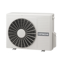
Specifications for RAC-25WXE, RAC-35WXE, and RAC-50WXE outdoor units.
Detailed dimensions and physical layout of RAK indoor units.
Dimensions and physical layout of RAC-25WXE and RAC-35WXE outdoor units.
Dimensions and physical layout of the RAC-50WXE outdoor unit.
Characteristic curves for cooling and heating capacities based on temperature.
Adjusting capacity based on piping length and defrosting operation.
Sound pressure levels for RAC-25WXE unit in cooling and heating modes.
Sound pressure levels for RAC-35WXE unit in cooling and heating modes.
Sound pressure levels for RAC-50WXE unit in cooling and heating modes.
Voltage requirements and temperature limits for unit operation.
Electrical data including power, fuse rating, and current for indoor/outdoor units.
Wiring schematic for the RAK indoor units.
Wiring schematic for the RAC outdoor units.
Diagrams illustrating the refrigerant flow for different unit models.
Explanation of buttons and features on the wireless remote control.
Automatic mode switching and adjustment of temperature shift values.
Locking operations and preventing interference between units.
Fan speed adjustments and troubleshooting error codes.
Configuring auto-restart and model selection using DIP switches.
Details and operation of the SPX-RCDB wired remote control.
Installation, safety, and wiring for the H-LINK Adaptor.
Using dry contact for external control with DIP switch settings.
Using the SPX-DST1 distributor for centralized control of multiple units.
| Brand | Hitachi |
|---|---|
| Model | RAC-25WXE |
| Category | Air Conditioner |
| Language | English |