SPECIFICATIONS AND PARTS ARE SUBJECT TO CHANGE FOR IMPROVEMENT
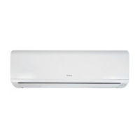
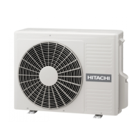
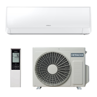
ROOM AIR CONDITIONER
INDOOR UNIT + OUTDOOR UNIT
SERVICE MANUAL
REFER TO THE FOUNDATION MANUAL
TECHNICAL INFORMATION
FOR SERVICE PERSONNEL ONLY
SPECIFICATIONS
CONTENTS
SPECIFICATIONS ------------------------------------------------------------------- 6
HOW TO USE ----------------------------------------------------------------------- 9
CONSTRUCTION AND DIMENSIONAL DIAGRAM --------------------- 18
MAIN PARTS COMPONENT --------------------------------------------------- 21
WIRING DIAGRAM ---------------------------------------------------------------- 23
CIRCUIT DIAGRAM --------------------------------------------------------------- 25
After installation
BLOCK DIAGRAM ----------------------------------------------------------------- 28
BASIC MODE ----------------------------------------------------------------------- 29
REFRIGERATING CYCLE DIAGRAM --------------------------------------- 39
DESCRIPTION OF MAIN CIRCUIT OPERATION ----------------------- 45
SERVICE CALL Q & A ---------------------------------------------------------- 70
TROUBLE SHOOTING ----------------------------------------------------------- 73
PARTS LIST AND DIAGRAM --------------------------------------------------105
HHAW
INDOOR UNITOUTDOOR UNIT
INDOOR UNIT OUTDOOR UNIT INDOOR UNIT OUTDOOR UNIT INDOOR UNIT OUTDOOR UNIT INDOOR UNIT OUTDOOR UNIT
RAK-18PEC RAC-18WEC
RAK-25PEC
RAK-25PECC
RAC-25WEC RAC-35WEC
RAC-10WECI RAC-14WECI
RAK-10PECI
RAK-35PEC
RAK-35PECC
RAK-14PECI
RAK-50PEC
RAK-50PECC
RAK-20PECI
RAC-50WEC
RAC-20WECI
(KW)
(B.T.U./h)
(KW)
(B.T.U./h)
W 780 660(+60) 780 660(+60) 780 660(+60) 780 792(+91)
H 280 530 280 530 280 530 280 600
D 218 278(+55) 218 278(+55) 218 278(+55) 218 299(+47)
MODEL
POWER SOURCE
TOTAL INPUT (W
TOTAL AMPERES (A)
CAPACITY
COOLING
HEATING
TOTAL INPUT (W
TOTAL AMPERES (A)
CAPACITY
1,090 (250
1,460)
DIMENSIONS
(mm)
1,560 (500 2,100)
3.19-3.05
2.00 (0.90
2.50)
6,820 (3,070
8,530)
620 (250
970)
2.50 (0.90
3.20)
3.62-3.46
7.5 24.5 7.5 24.5 7.5 27.5 40
8,530 (3,070
10,920)
880 (250
1,250)
NET WEIGHT (Kg)
TYPE
DC INVERTER
1 PHASE,50Hz ,220-230V 1 PHASE,50Hz ,220-230V 1 PHASE,50Hz ,220-230V 1 PHASE,50Hz , 220-230V
580 (
700 (250 1,290)1,010)
4.56-4.36
3.40 (0.90
4.40)
11,600 (3,070
15,010)
5.41-5.18
1,100 (250
1,700)
5.36-5.13
14,330 (3,070
17,060)
3.84-3.67
2.50 (0.90
3.10)
8,530 (3,070
10,580)
7.29-6.85
3.50 (0.90
4.00) 5.00 (1.90 5.20)
11,940 (3,070
13,650) 17,060 (6,480 17,740)
20,470 (7,510
24,910)
7.56-7.23
1,660 (500
2,750)
4.20 (0.90
5.00) 6.00 (2.20 7.30)
25
0
Hitachi Household Appliances(Wuhu) Co., Ltd.
NO. 0093E
8
PROCEDURE FOR DISASSEMBLY AND REASSEMBLY------------- 42
L.H
RAK-18PEC/RAC-18WEC
RAK-35PEC/RAC-35WEC
RAK-50PEC/RAC-50WEC
RAK-25PEC/RAC-25WEC
RAK-35PECC/RAC-35WEC
RAK-50PECC/RAC-50WEC
RAK-25PECC/RAC-25WEC
RAK-14PECI/RAC-14WECI
RAK-20PECI/RAC-20WECI
RAK-10PECI/RAC-10WECI
RAK-18PEC
RAK-25PEC
RAK-35PEC
RAK-50PEC
RAK-25PECC
RAK-35PECC
RAK-50PECC
RAK-10PECI
RAK-14PECI
RAK-20PECI
RAC-18WEC
RAC-25WEC
RAC-35WEC
RAC-10WECI
RAC-14WECI
RAC-50WEC
RAC-20WECI


 Loading...