– 4 –
NAMES AND FUNCTIONS OF EACH PART
INDOOR UNIT
Air filter
To prevent dust from coming into the indoor unit.
(Refer page 11)
Front panel
Indoor unit indicators
Light indicator showing the operating condition.
(Refer page 5)
Horizontal deflector Vertical deflector
(Air Outlet)
(Refer page 10)
Remote controller
Send out operation signal to the indoor unit. So as
to operate the whole unit.
(Refer page 6)
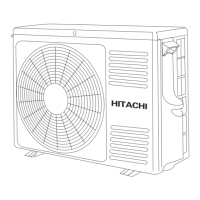
MODEL NAME AND DIMENSIONS
About the outdoor unit:
• When “Stop” is selected during operation
of the indoor unit, the fan of the outdoor
unit continues turning for 10 to 60
seconds to cool the electric parts down.
• In heating operation, condensate or
water due to defrosting will flow.
Do not cover the drain port of the outdoor
unit because such water may freeze in
the chilly area.
• When the outdoor unit is hung on the
ceiling, install the bush and drain pipe
on the drain port and drain water.
MODEL WIDTH (mm) HEIGHT (mm) DEPTH (mm)
780 280 210
700 505 258
750 548 288
Air outlet
When “heating” operation is
performed, cool air blows and
when “cooling” or “dehumidifying”
operation is performed, warm air
blows.
Drain hose
Drains the dehumidified water from the indoor unit to the
outdoor during “cooling” or “dehumidifying” operation.
Piping and Wiring
Air inlets (Rear and left sides)
Drain port
(Bottom)
Earth terminal
(Lower section of the side)
RAC-E14H3
RAC-E10H3
OUTDOOR UNIT
RAS-E10H3, RAS-E14H3
RAC-E14H3
RAC-E10H3
TEMPORARY
SWITCH