EasyManua.ls Logo

Hitachi RAF-50FX8 User Manual

Hitachi RAF-50FX8
190 pages
To Next Page IconTo Next Page
Page #1 background imageLoading...
Page #1 background image
TC NO. 0779EF
RAF-50FX8
RAC-50FX8
SERVICE MANUAL
TECHNICAL INFORMATION
INFORMATIONS TECHNIQUES
REFER TO THE FOUNDATION MANUAL
REPORTEZ-VOUS AU MANUEL DE BASE
ROOM AIR CONDITIONER
SPECIFICATIONS AND PARTS ARE SUBJECT TO CHANGE FOR IMPROVEMENT
LES SPECIFICATIONS ET PIECES DETACHEES PEUVENT CHANGER POUR ETRE AMELIOREES.
FOR SERVICE PERSONNEL ONLY
RESERVE AU PERSONNEL
SPECIFICATIONS
CARACTERISTIQUES GENERALES
SPECIFICATIONS‥‥‥‥‥‥‥‥‥‥‥‥‥‥‥‥‥‥‥
CARACTERISTIQUES GENERALES
HOW TO USE‥‥‥‥‥‥‥‥‥‥‥‥‥‥‥‥‥‥‥‥
UTILISATION
CONSTRUCTION AND DIMENSIONAL DIAGRAM‥‥‥‥
DIMENSIONS DES UNITÉS
MAIN PARTS COMPONENT‥‥‥‥‥‥‥‥‥‥‥‥‥‥
PRINCIPAUX COMPOSANTS
WIRING DIAGRAM‥‥‥‥‥‥‥‥‥‥‥‥‥‥‥‥‥‥
SCHÉMAS ÉLECTRIQUES
WIRING DIAGRAM OF THE PRINTED WIRING BOARD
‥‥‥
SCHÉMA ÉLECTRIQUE DU CIRCUIT IMPRIMÉ
BLOCK DIAGRAM‥‥‥‥‥‥‥‥‥‥‥‥‥‥‥‥‥‥
ORGANIGRAMME DE CONTROLE
BASIC MODE‥‥‥‥‥‥‥‥‥‥‥‥‥‥‥‥‥‥‥‥
MODE DE BASE
REFRIGERATING CYCLE DIAGRAM‥‥‥‥‥‥‥‥‥
SCHÉMA DU CYCLE DE RÉFRIGÉRATION
DISASSEMBLY&ASSEMBLYPROCEDURE‥‥‥‥‥‥
PROCEDURE D'ASSEMBLAGE ET DESASSEMBLAGE
DESCRIPTION OF MAIN CIRCUIT OPERATION‥‥‥‥
DESCRIPTION DES PRINCIPAUX CIRCUITS ÉLECTRIQUES
SERVICE CALL Q&A ‥‥‥‥‥‥‥‥‥‥‥‥‥‥‥‥
MODE OPERATOIRE DE DEPANNAGE
TROUBLE SHOOTING‥‥‥‥‥‥‥‥‥‥‥‥‥‥‥‥
DETECTION DES PANNES
PARTS LIST AND DIAGRAM‥‥‥‥‥‥‥‥‥‥‥‥‥
LISTE DES PIÉCES DE RECHANGE
CONTENTS
TABLE DES MATIERES
INDOOR UNIT + OUTDOOR UNIT
MARCH 2008 Hitachi Appliances, Inc.
8
9
32
36
39
43
53
57
82
84
94
156
164
204
OUTDOOR UNIT
UNITÉ EXTÉRIEURE
RAF-50FX8
RAC-50FX8
INDOOR UNIT
UNITÉ INTÉRIEURE
After installation Après installation
750
590
215
15
792 (+95)
600
299 (+46)
45
RAF-50FX8
TYPE TYPE
MODEL MODÈLE
POWER SOURCE  
SOURCED'ALIMENTATION(PHASE/TENSION/FREQUENCE)
TOTAL INPUT
PUISSANCE ABSORBEE TOTALE (W)
TOTAL AMPERES
AMPERES TOTAUX (A)
CAPACITY CAPACITE
(kW)
(B.T.U./h)
TOTAL INPUT
PUISSANCE ABSORBEE TOTALE (W)
TOTAL AMPERES
AMPERES TOTAUX (A)
CAPACITY CAPACITE
(kW)
(B.T.U./h)
W, L
DIMENSIONS DIMENSIONS (mm) H, H
D, P
NET WEIGHT POIDS NET (kg)
DC INVERTER   INVERSEUR C.C.
INDOOR UNIT
UNITÉ INTÉRIEURE
OUTDOOR UNIT
UNITÉ EXTÉRIEURE
1ø, 220V - 230V, 50Hz
1,560 (155 - 1,950)
7.16 - 6.85
5.0 (0.9 - 5.2)
17,065 (3,072 - 17,748)
1,780 (155 - 2,100)
8.17 - 7.82
6.5 (0.9 - 8.1)
22,185 (3,072 - 27,645)
COOLING
RÉFRIGÉRATION
HEATING
CHAUFFAGE
RAC-50FX8

Table of Contents

Question and Answer IconNeed help?

Do you have a question about the Hitachi RAF-50FX8 and is the answer not in the manual?

Hitachi RAF-50FX8 Specifications

General IconGeneral
Cooling Capacity5.0 kW
Heating Capacity6.0 kW
Power Supply220-240V, 50Hz
Energy Efficiency Ratio (EER)3.21
Coefficient of Performance (COP)3.61
RefrigerantR410A
Indoor Unit Weight11 kg
Noise Level (Outdoor Unit)52 dB(A)
Outdoor Unit Dimensions (W x H x D)780 x 540 x 285 mm
Noise Level (Indoor Unit)46 dB(A)
TypeSplit System Air Conditioner

Summary

CONTENTS

SPECIFICATIONS

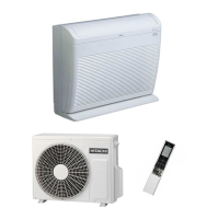
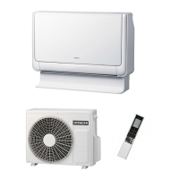
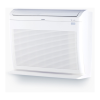
General characteristics and specifications of the air conditioner unit.

HOW TO USE

Instructions for operating the air conditioner.

CONSTRUCTION AND DIMENSIONAL DIAGRAM

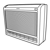
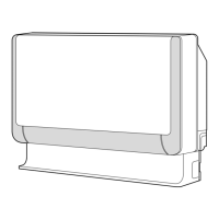
Details on the unit's construction and dimensions.

MAIN PARTS COMPONENT

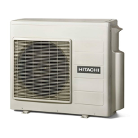
Identification of the main components of the unit.

WIRING DIAGRAM

Electrical wiring schematic for the unit.

BLOCK DIAGRAM

Functional block diagram of the air conditioner system.

BASIC MODE

Explanation of basic operating modes.

REFRIGERATING CYCLE DIAGRAM

Diagram illustrating the refrigeration cycle.

DISASSEMBLY & ASSEMBLY PROCEDURE

Step-by-step guide for disassembling and assembling the unit.

DESCRIPTION OF MAIN CIRCUIT OPERATION

Explanation of how the main electrical circuits operate.

TROUBLE SHOOTING

Guidance for diagnosing and resolving common issues.

SAFETY DURING REPAIR WORK

General Repair Safety Precautions

Essential safety guidelines to follow before and during repair work.

WORKING STANDARDS FOR PREVENTING BREAKAGE OF SEMICONDUCTORS

ATTENTION

HOW TO USE

SAFETY PRECAUTION

Important safety information to read before operating the unit.

PRECAUTIONS DURING OPERATION

Safety measures to observe while the unit is running.

PRECAUTIONS DURING INSTALLATION

Safety guidelines for installing the air conditioner.

PRECAUTIONS DURING SHIFTING OR MAINTENANCE

Safety advice for moving or maintaining the unit.

NAMES AND FUNCTIONS OF EACH PART

NAMES AND FUNCTIONS OF EACH PART (Continued)

REMOTE CONTROLLER Functions

Explanation of the remote control's buttons and functions.

HEATING OPERATION

DEHUMIDIFYING OPERATION

COOLING OPERATION

FAN OPERATION

HOW TO SET THE TIMER

HOW TO SET THE SLEEP TIMER

ADJUSTING THE AIR DEFLECTORS

HOW TO CHANGE THE BATTERIES IN THE REMOTE CONTROLLER

HOW TO USE THE AIR CONDITIONER EFFECTIVELY

Tips for maximizing efficiency and effectiveness of the air conditioner.

1. AIR FILTER Maintenance

2. HOW TO INSTALL AND REMOVE THE FRONT PANEL

TIMER PROGRAMMING/SLEEP TIMER OPERATION

REGULAR INSPECTION

WHEN ASKING FOR SERVICE, CHECK THE FOLLOWING

AFTER SALES SERVICE AND WARRANTY

CONSTRUCTION AND DIMENSIONAL DIAGRAM

DIMENSIONNS DES UNITES

MAIN PARTS COMPONENT

FAN MOTOR Specifications

Specifications and characteristics of the fan motor.

COMPRESSOR

WIRING DIAGRAM

WIRING DIAGRAM OF THE PRINTED WIRING BOARD

BLOCK DIAGRAM

BASIC MODE

Basic Cooling Operation

Cooling Sleep Operation

Cooling Defrost

Dehumidifying

Dehumidifying Sleep Operation

Heating Basic Operation

Reversing Valve Defrosting

Setting Defrosting Inhibit Period

COOLING CYCLE

HEATING CYCLE

DISASSEMBLY & ASSEMBLY PROCEDURE

1. AIR FILTER Maintenance

Instructions for cleaning the air filter.

3. Remove the front cover

4. Install the front cover

9. FAN MOTOR AND TANGENTIAL AIR FLOW FAN

DESCRIPTION OF MAIN CIRCUIT OPERATION

1. Power circuit

Detailed explanation of the power circuit's operation.

2. Reset Circuit

3. Room Temperature Thermistor Circuit

4. Heat Exchanger Thermistor Circuit

5. Humidity Sensor Circuit

6. Fan Motor Drive Circuit

9. Initial Setting Circuit (IC401)

10. Temporary Switch Circuit

1. Power Circuit

2. Indoor/Outdoor Interface Circuit

Fig. 2-1 Indoor/outdoor interface Circuit

Fig. 2-2 Voltages Waveforms of indoor / Outdoor Microcomputers (Outdoor to Indoor Communications)

[Serial Communications Format during Normal Communications]

3. Power Module Circuit

Fig. 3-2 Switching order of power module

Fig. 3-3 Voltage waveform at each point

Fig. 3-4 Power module circuit (U+ is ON, V- is ON)

4. Power Circuit for P.W.B.

5. Reversing valve control circuit

6. Drive Circuit

7. HIC and Peripheral Circuits

Fig. 7-1 Microcomputer (AX-8T11) and Peripheral Circuits

Schematic of microcomputer and its peripheral circuits.

The following describes the operation of ecah circuit in detail.

(1) Peak current cut off circuit

Explanation of the peak current cut off circuit's function.

(2) Overload control circuit (OVL control circuit)

Fig. 7-4 Overload Control System Configuration

② Voltage amp. circuit

<During start current control>

8. Temperature Detection Circuit

9. Reset Circuit

10. Outdoor DC Fan Motor control circuit

11. Power Factor Control Circuit

12. Increasing DC Voltage (Vd)

SERVICE CALL Q&A

COOLING MODE Issues

Troubleshooting common problems during cooling operation.

DEHUMIDIFYING MODE Issues

Troubleshooting common problems during dehumidifying operation.

HEATING MODE Issues

Troubleshooting common problems during heating operation.

AT STARTING OPERATION

TROUBLE SHOOTING

PRECAUTIONS FOR CHECKING

Procedures for Electrical Discharge and How to Stop Energizing the Power Circuit

Self Diagnosis Indicating Function (Indoor Unit)

Self Diagnosis Memory Function

Re-indication method for defective mode

Procedure to re-display past detected malfunctions via remote.

Clear method for data of defective mode

Procedure to clear stored defective mode data.

CHECKING THE OUTDOOR UNIT ELECTRICAL PARTS

Operate the outdoor unit according to the instruction "How to operate the outdoor unit independently"

Procedure for independent operation of the outdoor unit for testing.

LD301 blinks 8 times. Acceleration defect.

LD301 blinks 2 times. Peak current-cut.

LD301 blinks 1 time. Reset stop.

POWER CIRCUIT

PHENOMENON 1 <ROTATION SPEED DOES NOT INCREASE>

Troubleshooting steps for 'Rotation Speed Does Not Increase' error.

HOW TO CHECK POWER MODULE

HOW TO OPERATE USING THE SERVICE SWITCH THE OUTDOOR UNIT

HOW TO OPERATE THE OUTDOOR UNIT INDEPENDENTLY

PARTS LIST AND DIAGRAM

PARTS LIST AND DIAGRAM (Continued)

Related product manuals