EasyManua.ls Logo

Hitachi RAK-18QXB User Manual

Hitachi RAK-18QXB
92 pages
To Next Page IconTo Next Page
Page #1 background imageLoading...
Page #1 background image
SPECIFICATIONS AND PARTS ARE SUBJECT TO CHANGE FOR IMPROVEMENT
ROOM AIR CONDITIONER
INDOOR UNIT
SERVICE MANUAL
REFER TO THE FOUNDATION MANUAL
TECHNICAL INFORMATION
FOR SERVICE PERSONNEL ONLY
SPECIFICATIONS
CONTENTS
SPECIFICATIONS ------------------------------------------------------------------- 6
HOW TO USE ---------------------------------------------------------------------- 9
CONSTRUCTION AND DIMENSIONAL DIAGRAM --------------------- 29
MAIN PARTS COMPONENT --------------------------------------------------- 30
WIRING DIAGRAM ---------------------------------------------------------------- 31
CIRCUIT DIAGRAM --------------------------------------------------------------- 33
After installation
BLOCK DIAGRAM ----------------------------------------------------------------- 35
BASIC MODE ----------------------------------------------------------------------- 36
REFRIGERATING CYCLE DIAGRAM --------------------------------------- 47
DESCRIPTION OF MAIN CIRCUIT OPERATION ----------------------- 51
SERVICE CALL Q & A ---------------------------------------------------------- 61
HHAW
INDOOR UNIT
INDOOR UNIT OUTDOOR UNIT INDOOR UNIT OUTDOOR UNIT INDOOR UNIT OUTDOOR UNIT
RAK-25R RAC-25W RAK-35R RAC-35W RAK-50R RAC-50W
(KW)
(B.T.U./h)
(KW)
(B.T.U./h)
W
295
210
11
750(+65)
548
288(+27.5)
34
H
D
MODEL
POWER SOURCE
TOTAL INPUT (W)
TOTAL AMPERES (A)
CAPACITY
COOLING
HEATING
TOTAL INPUT (W
TOTAL AMPERES (A)
CAPACITY
910 (250
1,400)
DIMENSIONS
(mm)
1,560 (500 2,100)
700 (250
1,200)
NET WEIGHT (Kg)
TYPE
DC INVERTER
1 PHASE,50HZ,220-230V 1 PHASE,50HZ,220-230V 1 PHASE,50HZ,220-230V
545 (250
1,220)
3.85-3.68
3.20 (0.90
4.20)
10,920 (3,070
14,330)
4.81-4.60
95 (250
1,600)
4.93-4.72
14,330 (3,070
16,380)
3.19-3.05
2.50 (0.90
3.10)
8,530 (3,070
10,580)
7.30-6.98
3.50 (0.90
4.00) 5.00 (1.90 5.20)
11,940 (3,070
13,650 ) 17,060 (6,480 17,740)
20,470 (7,510
24,910)
7.45-7.12
1,560 (500
2,700)
4.00 (0.90
4.80) 5.80 (2.20 7.00)
Hitachi Household Appliances(Wuhu) Co., Ltd.
XB XB XB XB XB XB
RAK-35RXB
RAK-25RXB
RAK-18QXB
RAK-50RXB
295
210
11
750(+65)
548
288(+27.5)
34
900
295
210
11
800(+63)
736
350(+35.5)
49.5
RAK-35RXB
RAK-50RXBRAK-25RXB
RAK-18QXB
PROCEDURE FOR DISASSEMBLY AND REASSEMBLY------------- 49
RAK-18QXB RAK-25RXB RAK-35RXB RAK-50RXB
-
RAC-25WXB RAC-35WXB RAC-50WXB
RAM-33NP2B
o o
- -
RAM-40NP2B
o o o
-
RAM-53NP2B
o o o o
RAM-53NP3B
o o o o
RAM-68NP3B
o o o o
RAM-70NP4B
o o o o
RAM-90NP5B
o o o o
RAM-110NP6B
o o o o
Single outdoor unit
Multi
outdoor
unit
Indoor unit
RAC-25WXB,RAC-35WXB,RAC-50WXBHHAW NO.0081E
This manual describes only points that differ from
for items not described in this manual.
5
RAM-33NP2BPM NO.0581E
RAM-40NP2BPM NO.0582E
RAM-53NP2B,RAM-53NP3BPM NO.0583E
RAM-110NP6B
PM NO.0584ERAM-68NP3B
PM NO.0585ERAM-70NP4B
PM NO.0586ERAM-90NP5B
PM NO.0587E
PARTS LIST AND DIAGRAM --------------------------------------------------
VARIOUS SETTINGS ----------------------------------------------------------------- 71
900900
- 1 -
NO.0088E-1
90
Question and Answer IconNeed help?

Do you have a question about the Hitachi RAK-18QXB and is the answer not in the manual?

Hitachi RAK-18QXB Specifications

General IconGeneral
Capacity1.5 Ton
Star Rating3 Star
Outdoor Unit Weight30 kg
RefrigerantR32
Power Supply50 Hz

Summary

Safety Information

SAFETY DURING REPAIR WORK

Essential safety guidelines for personnel performing repairs.

SAFETY PRECAUTION

General safety instructions for unit usage and installation.

Specifications and Components

SPECIFICATIONS

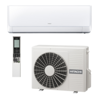
Detailed technical specifications of the unit.

NAMES AND FUNCTIONS OF EACH PART

Identification of indoor unit parts and indicators.

MAIN PARTS COMPONENT

Key internal components like thermostat and fan motor specs.

PARTS LIST AND DIAGRAM

Exploded view and part number list for indoor unit components.

Remote Controller Operation

Remote Controller Manual

Comprehensive guide for remote controller usage.

PREPARATION BEFORE OPERATION

Steps for installing batteries and mounting the controller holder.

NAMES AND FUNCTIONS OF REMOTE CONTROLLER

Overview of remote buttons, display, and core functions.

HOW TO CHANGE THE SHIFT VALUE SETTING TEMPERATURE

Procedure to adjust temperature shift values for cooling/heating.

SETTING THE PREVENTION OF MUTUAL INTERFERENCE FOR REMOTE CONTROLLER

Guide to changing remote controller signal addresses.

Sources of Remote Control Signal Interference

Identifying external factors affecting remote control signal reception.

Unit Operation Modes and Features

HEATING OPERATION

Guidelines for operating the unit in heating mode.

COOLING OPERATION

Guidelines for operating the unit in cooling mode.

DEHUMIDIFYING OPERATION

Guidelines for dehumidifying operation.

FAN OPERATION

Instructions for using the unit as a fan.

BASIC MODE

Explanation of basic operation modes and fan speed.

POWERFUL OPERATION

Using the powerful mode for rapid cooling or heating.

SILENT OPERATION

Activating silent mode for reduced noise.

ECO OPERATION

Energy-saving mode by adjusting settings automatically.

LEAVE HOME (LH) OPERATION

Maintaining room temperature when unoccupied.

CLEAN (ONE TOUCH CLEAN) OPERATION

Procedure for cleaning the indoor unit's heat exchanger.

ONCE TIMER (ON/OFF TIMER) OPERATION

Setting on/off timers for specific times.

ECO SLEEP TIMER OPERATION

Setting a timer for energy-saving sleep operation.

WEEKLY TIMER OPERATION

Setting daily and weekly timer programs.

Reversing valve defrosting

Explains the defrosting process for different models.

Diagrams and Electrical Schematics

CONSTRUCTION AND DIMENSIONAL DIAGRAM

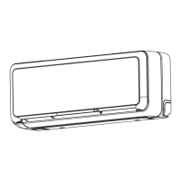
Visual representation of the indoor unit's physical dimensions.

WIRING DIAGRAM

Electrical wiring schematic for the indoor unit.

CIRCUIT DIAGRAM

Detailed circuit diagrams for specific indoor unit models.

BLOCK DIAGRAM

Functional block diagram of the indoor unit's electrical system.

REFRIGERATING CYCLE DIAGRAM

Illustrates the cooling and heating cycles of the system.

DESCRIPTION OF MAIN CIRCUIT OPERATION

Explanation of the main circuit's power supply and operation.

Reset Circuit

Description of the circuit for initializing the microcomputer.

Drive circuit of the indoor fan motor

Explanation of the circuit controlling the indoor fan motor.

Buzzer Circuit

Details on the circuit that generates buzzer sounds.

Remote control reception circuit

Explanation of how remote control signals are received.

Initial Setting Circuit

Circuit for initial setup and compressor settings.

Room Temperature Thermistor Circuit

Circuit for room temperature sensing.

Heat Exchanger Thermistor Circuit

Circuit for heat exchanger temperature sensing.

Dip-switch

Explanation of dip switch functions and settings.

Indoor/outdoor communication circuits

How indoor and outdoor units communicate.

Stepping motor drive circuit

Circuit controlling air deflector motors.

Infrared human presence sensor circuit

Circuit for detecting human presence for energy saving.

Troubleshooting and Service

SERVICE CALL Q&A

Common questions and answers for operational issues.

Troubleshooting support

Overview of self-diagnosis functions and memory.

Self-diagnosis display function (indoor side display)

How to interpret indoor unit self-diagnosis indications.

SELF-DIAGNOSIS MEMORY FUNCTION

How to access and clear stored failure data.

Forced cooling operation (Only single connection)

Procedure for forced cooling for maintenance.

Diagnosis and troubleshooting of indoor electrical parts

Flowchart for diagnosing indoor unit electrical failures.

Failure phenomenon: The power will not become turned on.

Troubleshooting steps for power-on issues.

Failure phenomenon: The product will not receive a remote control signal.

Troubleshooting steps for remote control reception issues.

Failure phenomenon: The compressor will not run.

Troubleshooting steps when the compressor does not operate.

Failure phenomenon: The fan motor will not stop.

Troubleshooting steps for a continuously running fan motor.

Failure phenomenon:The eco sensor lamp is blinking.

Troubleshooting for eco sensor issues.

Timer lamp blinking: blinking three times

Troubleshooting for timer lamp blinking 3 times.

Timer lamp blinking: blinking 9 times

Troubleshooting for timer lamp blinking 9 times.

Timer lamp blinking: blinking 10 times

Troubleshooting for timer lamp blinking 10 times.

Timer lamp blinking: blinking 12 times

Troubleshooting for timer lamp blinking 12 times.

Disassembly and Reassembly

Procedure for Disassembly and Reassembly

Step-by-step guide for disassembling and reassembling the indoor unit.

Related product manuals