Please mount the Outdoor unit of stable ground to prevent vibration and increase
of noise level.
Decide the location for piping after sorting out the different types of pipe available.
When removing side cover, please pull the handle after undoing the hook by pulling
it downward. Reinstall the side cover in the reverse order of the removal.
CONDENSED WATER DISPOSAL OF OUTDOOR UNIT
There is holes on the base of Outdoor unit for condensed water to exhaust.
In order to flow condensed water to the drain, the unit is installed on a stand or a
block so that the unit is 100mm above the ground as shown figure. Join the drain
pipe to one hole.
After installation, check whether the drain pipe clings to the base firmly.
Install the outdoor unit horizontally and make sure that condensate drains away.
In case of using in chilly area
Especially, in case that there are many snows by very cold in chilly area, condensed
water freezes on the base and may result not to drain. In this case, please remo
ve
the bush and the drain pipe at the bottom of unit. (Left and center near discharge
portion of air, each 1 place). It becomes smooth drain.
Ensure that the distance from the drain hole to the ground is 250 mm or more.
CAUTION
Remove burr and jagged edge will cause leakage.
Point the side to be trimmed downwards during trimming to prevent copper
chips from entering the pipe.
Copper pipe
Trimming tool
Before flaring, please put on the flare nut.
A
Die
Die
Copper pipe
2 Pipe Connection
CAUTION
In case of removing flare nut of a indoor unit, first remove
a nut of small diameter side, or a seal cap of big diameter
side will fly out. Free from water into the piping when
working.
Be sure to tighten the flare nut to the specified torque with
a torque wrench.
If the flare nut is overtightened, the nut may be split after a
long period has passed, and may cause a refrigerant leak.
Please be careful when bending the copper pipe.
Screw in manually while adjusting the center. After that, use a torque wrench to
tighten the connection.
OME
R RIA
DNA SE
PIP GN
ITARE
GIRFE
R FO N
OITALL
ATSN LI
AV
Torque
wrench
Flare nut
Wrench
3 Remove of Air From The Pipe And Gas Leakage Inspection
LA
VOME
R RIA
Procedures of using Vacuum Pump for Air Removal
As shown in right figure, remove the cap
of valve core. Then, connect the charge
hose. Remove the cap of valve head.
Connect the vacuum pump adapter to the
vacuum pump and connect the charge
hose to the adapter.
1
Fully tighte the "Hi" shuttle of the manifold
valve and completely unscrew the "Lo"
shuttle. Run the vacuum pump for about
10-15 minutes, then completely tighten the
"Lo" shuttle and switch off the vacuum
pump.
Loosen the spindle of the service valve
with small diameter by 1/4 turn and
tighten the spindle immediately after 5
to 6 seconds.
Remove the charging hose from the
service valve.
2
Completely unscrew the spindle of the
service valve (at 2 places) in anticlockwise
direction to allow the flow of refrigerant
(using Hexagonal Wrench key).
3
Tighten the cap of valve head. Check the
cap's periphery if there is any gas leakage.
The task is then completed.
4
The body of service
valve
Cap of
valve core
Hexagonal
wrench Key
Cap of valve
head
Gas leakage inspection
Please use gas leakage detector to check if leakage
occurs at
connection of Flare nut as shown on the
right.
If gas leakage
occurs, further tighten the connection
to stop leakage.
DROC REWOP FO NOITCENNOC
WARNING
TINU ROODTUO
NOITALLATSNI FO EGATS LANIF
1 Preparation of Pipe
Use a pipe cutter to cut the copper pipe and remove burr.
Power Source And Operation Test
WARNING
THIS APPLIANCE MUST BE
EARTHED.
Procedures of Wiring
Cap of valve
head
CAUTION
Do not touch the suction
por t, bottom surface, or
aluminum fin of the outdoor
unit.
Failure to do so may cause
an injury.
WARNING
Leave some space in the connecting cord for maintenance
purpose and be sure to secure it with the cord band.
Secure the connecting cord along the coated part of the wire
using the cord band. Do not exert pressure on the wire as this
may cause overheating or fire.
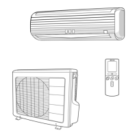
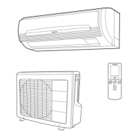
Indoor Unit Outdoor Unit
WARNING
If you cannot attach the side plate due to the connection cord, please
press the connecting cord in the direction to the front panel to fix it.
Be sure that the hooks of the side cover fixed in certainly. Otherwise water
leakage may occur and this causes short circuit or faults.
The connecting cord should not touch to service valve and pipes. (it
becomes high temperature in heating operation.)
Wiring of the Outdoor Unit
Please remove the side cover for wire connection.
Checking for the electric source and the voltage range
Before installation, the power source must be checked and necessary wiring work must
be completed. To make the wiring capacity proper, use the wire gauge list below for the
wiring from house distribution fuse box to the outdoor unit in consideration of the blocked
rotor current.
Investigate the power supply capacity and other
electrical conditions at the installing location.
Depending on the model of room air conditioner to be
installed, request the customer to make arrangements
for the necessary electrical work etc.
The electrical work includes the wiring work up the
outdoor unit. In localities where electrical conditions
are poor, use of a voltage regulation is recommended.
Install outdoor for the room air conditioner within the
reaching range of the line cord.
IMPORTANT
Fuse Capacity
1 A time delay fuse
Push up the [PUSH] sections at the bottom of the indoor unit and
pull the bottom plate towards you. Then the claws are released
from the stationary plate.
(The [PUSH] sections are indicated by 2 arrows in the right figure)
HOW TO REMOVE INDOOR UNIT
Wiring of The Indoor Unit
For wire connection of the Indoor unit, you need to remove the front cover, the low cover
under the body of the unit and terminal cover.
The naked part of the wire core should be 10mm fix it to the terminal tightly. Then
try to pull the individual wire to check if the contact is tight. Improper insertion may
burn the terminal.
Be sure to use only wire specified for the use of air-conditioner.
Please refer to the manual for wire connection and the wiring technique should
meet the standard of the electrical installation.
There is an AC voltage drop between the LN terminal if the power is on. Therefore,
be sure to remove the plug from its socket.
For cable connection to control P.W.B., you need to
remove front cover and electrical box cover.
Each connecting location is as below.
Wired Remote Control : CN20
Please check and confirm manuals attached to each
optional parts for more connection details.
You can refer to this installation manual how to remove
and re-attach the front cover.
Please be careful not to damage lead wires by edge of
plate when connecting the optional parts.
Remove the cover from the terminal base and screw the cable.
Method to remove the low cover
Pull at the and in
the directions as shown
by arrows to remove the
cover.
5
ler
above
BASE
Outer diameter:
16 mm or more
When the meter reaches - 101KPa
(-76cmHg) during pumping lly
tighten the shuttle.
Meter showing
pressure
Closed
Manifold
valve
Vacuum
pump
Valve
Charge
hose
Vacuum
pump
adapter
When pumping starts, slightly
loosen the flare nut to check of
air sucked in. Then tighten the
flare nut.
Valve
70mm
Please face this side (suction side)
of the unit to the wall.
Please remove terminal cover
when connecting the piping
and connecting cord.
Pull downward
L N
Connecting Cord
AC 220-230V
1ø 50Hz
1 2 3
1 2 3
Detail of Cutting the Connecting Cord
cover
Cord band
Earth terminal
7 DRAIN PIPE
160mm
10mm
100mm
1
2
3
70mm
10mm
10mm
45mm
1
2
3
Connecting cord
Strip
wires
Green +
Yellow
20mm
Strip
wires
Connecting cord
Green + Yellow
(ground)
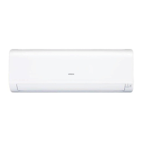
Indoor Unit
Outdoor Unit
WARNING
When the fuse (F5 or F6) has been blown out by the improper connection of
power cable, it can be restored by
RAK_RAS_18/25/35/50PEC_IM_English
Pull downward
Please face this side (suction side)
of the unit to the wall.
Please remove terminal cover
when connecting the piping
and connecting cord.
BUSH
Push Push
DRAIN HOLE
DRAIN HOLE
above
100mm
BASE
Outer diameter:
16 mm or more
7 DRAIN PIPE
6.35 (1/4")
9.52 (3/8")
12.7 (1/2")
6.35 (1/4")
9.52 (3/8")
13.7-18.6 (140 - 190)
34.3-44.1 (350 - 450)
44.1-53.9 (450 - 550)
19.6-24.5 (200 - 250)
19.6-24.5 (200 - 250)
12.7 (1/2")
12.3-15.7 (125 - 160)
Small diameter side
Outer diameter
of pipe (ø)
Large diameter side
Small diameter side
Large diameter side
Valve core cap
Torque N·m
(kgf·cm)
Valve
head cap
29.4-34.3 (300 - 350)
L N 1 2 3
Abdeck
L N 1
2
3
cover
Earth terminal
Cord band
A time delay fuse25
Wire length
up to 6m 1.5mm
2
up to 15m 2.5mm
2
up to 20m 4.0mm
2
Wire cross-section
How to connect the optional parts
Dry contact: CN6
Terminal marking
s Please ensure that the air conditioner is in normal operating
condition during the operation test.
s Explain to your customer about the proper operation procedures
as described in the operation manual.
s If the indoor unit won’t operate, check the cable for correct
connection.
Power Source
WARNING
Never remodel the power plug nor extend the long-distance
cord.
Keep additional length for the power cord and do not render
the plug under external force as this may cause poor contact.
Do not fix the power cord with U-shape nail.
The power cable easily generates heat. Do not bring the
cable together with a wire or vinyl tie.
Operation test
2
8
RAC-18/25/35WED
RAC-50WED
RAC-50WED
RAC-18/25/35WED
RAC-18/25/35WED
RAC-50WED
RAC-18/25/35WED
RAC-50WED
BUSH
8
(WIFI Adapter, H-LINK RAC Adapter, Dry contact, Wired Remote Controller)
WIFI Adapter H-LINK RAC Adapter: CN7 or
6,35 (1/4")
9,52 (3/8")
0 - 0,5
0 - 0,5
1,0
1,0
0 - 0,5
1,0
12,7 (1/2")
Outer A (mm) Rigid Flaring Tool
Diameter (Ø) For R410A,R32 tool For R22 tool
Please use
exclusive tool for
refrigerant R410A,
R32.
R410A,R32
[PUSH] mark positions
exchanging the fuse (service part No
HWRAC-50NX 2 A52)
,fu
n
Connecting
cord
Cord band
After remove the screw
and terminal cover, and
put the connecting cords
and fix the terminal cover
with screw.
Earth
Please exchange the blown-out fuse after making sure the right connection.
CN7
CN20
CN6
How to remove the front cover How to Attach the Front Cover
After installing the front cover onto the unit, hook three claws
at upper side of the cover securely. Then, push the center of
the front cover to lock the claws.
Tighten the 3
Assemble the cover of electric box.
screws.
Install the filter.
Remove the filters.
After removing 3 screws,
pull
the
the
center of the front cover towards you and release
Pull the side faces (lower sections) of the front cover towards
you as shown in the figure and remove the cover.
1
2
Remove the front panel
Push the end of the right-side arm outward to release the
tab.
Move the left-side arm outward to release the left tab, and
then pull the panel towards you.
Insert the shaft of the left arm along the step on the unit into
the hole.
Securely insert the shaft of the right arm along the step on
the unit into the hole.
Make sure that the front panel is securely attached, and then
close the front panel.
Attaching the Front Panel
1
2
Push
Arm
SClaw
Claw
Claw
Claw
crew
Screw
remove the cover of electric box,
claws.
cover
 Loading...