EasyManua.ls Logo

Hitachi RAK-25PSEW User Manual

Hitachi RAK-25PSEW
142 pages
To Next Page IconTo Next Page
Page #1 background imageLoading...
Page #1 background image
INDOOR UNIT OUTDOOR UNIT
I N D O O R U N I T O U T D O O R U N I T
INDOOR UNIT OUTDOOR UNIT INDOOR UNIT OUTDOOR UNIT
RAK-25PSEW
RAK-25PSES
RAC-25WSE
RAK-35PSEW
RAK-35PSES
RAC-35WSE
RAK-50PSEW
RAK-50PSES
RAC-50WSE
(KW)
(B.T.U./h)
(KW)
(B.T.U./h)
W 795 792 795 792 795 800
H 250 600 250 600 250 736
D 294 299 294 299 294 350
11 37 11 37 11 51
7.38-7.06
6.00(2.207.00)
20,470(7,51023,380)
778
3.56-3.40
3.50(0.504.10)
11,940(1,71013,990)
800
3.65-3.50
DIMENSIONS(mm)
NET WEIGHT (kg)
490
2.26-2.16
2.50(0.503
.40)
8,530(1,71011,600)
621
2.85-2.73
3.20(0.605.80)
10,920(2,05019,790)
TOTAL INPUT (W)
TOTAL AMPERES (A)
COOLING
CAPACITY
HEATING
TOTAL INPUT (W)
TOTAL AMPERES (A)
CAPACITY
MODEL
DC INVERTER
TYPE
POWER SOURCE 1PHASE,50HZ,220V-230V 1PHASE,50HZ,220V-230V 1PHASE,50HZ,220V-230V
4.00(0.606.60)
13,650(2,05022,520)
1,389
6.33-6.05
5.00(1.
905.20)
17,060(6,48017,740)
1,622
After installation
REFER TO THE FOUNDATION MANUAL
CONTENTS
SPECIFICATIONS
HOW TO USE
CONSTRUCTION AND DIMENSIONAL DIAGRAM
MAIN PARTS COMPONENT
WIRING DIAGRAM
WIRING DIAGRAM OF THE PRINTED WIRING BOARD
BLOCK DIAGRAM
BASIC MODE
REFRIGERATING CYCLE DIAGRAM
DESCRIPTION OF MAIN CIRCUIT OPERATION
SERVICE CALL Q&A
TROUBLE SHOOTING
PARTS LIST AND DIAGRAM
36
38
62
136
6
33
46
103
9
45
67
63
98
PROCEDURE FOR DISASSEMBLY AND REASSEMBLY
41
RAC-25WSE
RAC-35WSE
RAC-50WSE
RAR-6NE2
RAK-25PSEW / RAC-25WSE
RAK-35PSEW / RAC-35WSE
RAK-50PSEW / RAC-50WSE
RAK-25PSES / RAC-25WSE
RAK-35PSES / RAC-35WSE
RAK-50PSES / RAC-50WSE
NO.0124EJCH-WH
INDOOR UNIT + OUTDOOR UNIT
RAK-25PSEW
RAK-35PSEW
RAK-50PSEW
RAK-25PSES
RAK-35PSES
RAK-50PSES
1
Question and Answer IconNeed help?

Do you have a question about the Hitachi RAK-25PSEW and is the answer not in the manual?

Hitachi RAK-25PSEW Specifications

General IconGeneral
Cooling Capacity2.5 kW
Heating Capacity3.2 kW
Energy Efficiency Class (Cooling)A++
Energy Efficiency Class (Heating)A+
RefrigerantR32
Power Supply220-240V, 50Hz
Indoor Unit Dimensions (W x H x D)780 x 280 x 230 mm
Noise Level (Outdoor)50 dB(A)

Summary

Safety During Repair Work

Working Standards for Preventing Breakage of Semiconductors

Items to be Observed in Handling

Specific practices for safely carrying, storing, and working with semiconductor parts.

Specifications

Figure Showing the Installation of Indoor and Outdoor Unit

Remote Controller Manual

Preparation Before Operation

Initial setup steps for the remote controller, including battery installation and mounting.

Names and Functions of Remote Controller

Various Functions

Auto Restart Control

How the unit automatically resumes operation after a power interruption.

Heating Operation

Dehumidifying Operation

Defrosting

Process of removing frost during dehumidification operation.

Cooling Operation

Frost Wash Operation

Frost Wash (Auto mode)

Automatic operation of the Frost Wash function for heat exchanger cleaning.

Frost Wash (Manual mode)

Procedure for manually initiating the Frost Wash function.

Filter Cleaning Operation (Automatic Operation)

Filter Cleaning Operation (Manual Operation)

Precautions for Use

Important safety and operational notes for manual filter cleaning.

Fan Operation

Auto Swing Operation

How to activate and control the automatic swing function for air direction.

ECO Operation

Powerful Operation

Leave Home Operation

ON/OFF Timer Operation

How to set automatic start and stop times for the air conditioner.

ECO Sleep Timer Operation

Weekly Timer Operation

Info Function

Operation Mode Lock Operation

Safety Precaution

Precautions During Installation

Critical safety steps and prohibitions to follow during the unit's installation process.

Precautions During Operation

Guidelines for safe and correct use of the air conditioner during its operation.

Names and Functions of Each Part

Indoor Unit

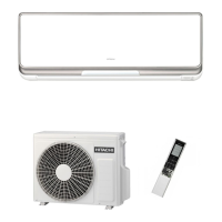
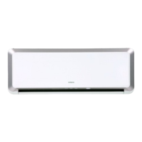
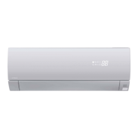
Identification and description of the main components of the indoor unit.

Outdoor Unit

Identification and description of the main components of the outdoor unit.

Model Name and Dimensions

Maintenance

Maintenance of Dust Box

Instructions for cleaning the dust collection box to ensure proper filter function.

Maintenance of Micro Mesh Stainless Filter

Maintenance of Dust Catcher

Understanding the Operating Mechanism

Heating Capability

How the unit provides heat and factors affecting its performance in cold weather.

Trouble Shooting

Filter Cleaning Operation

Troubleshooting steps related to the automatic and manual filter cleaning functions.

Frost Wash Operation

Regular Inspection

Inspection and Maintenance

Construction and Dimensional Diagram

Main Parts Component

Thermostat Specifications

Detailed specifications for the thermostat component.

Fan Motor

Details about the fan motor specifications, power source, and connection.

Compressor Motor

Wiring Diagram

Indoor Unit

Electrical schematics illustrating the internal connections of the indoor unit.

Wiring Diagram

Outdoor Unit

Electrical schematics illustrating the internal connections of the outdoor unit.

Wiring Diagram of the Printed Wiring Board

Block Diagram

Basic Mode

Basic Cooling Operation

Cooling Powerful Operation

Cooling Sleep Operation

Sleep timer function for cooling mode, adjusting settings for comfort and energy saving.

Basic Dehumidifying Operation

Basic Heating Operation

Reversing Valve Defrosting

Heating Sleep Operation

Sleep timer function for heating mode.

Heating Powerful Operation

Powerful mode for heating to achieve target temperature quickly.

Setting Defrosting Inhibit Period

Frost Wash

Pre-filter Cleaning System Operation Control (1)

Types of Cleaning Operation

Description of automatic, forcible, and manual cleaning types for the filter.

Operation Conditions

Conditions under which the filter cleaning system operates.

Refrigerating Cycle Diagram

Procedure for Disassembly and Reassembly

1. Front Panel

Detailed procedure for removing and reinstalling the front panel of the indoor unit.

2. Fancy Cover

Steps for removing and reinstalling the fancy cover and terminal board cover.

3. Cleaning Unit

8. WIFI Adapter Installation

Procedure for Disassembly and Reassembly

OUTDOOR UNIT 1. Electrical Parts

Procedure for accessing and removing electrical parts from the outdoor unit.

Description of Main Circuit Operation

1. Control Power Circuit

Detailed description of the control power circuit and its function.

2. Reset Circuit

3. Drive Circuit of the Indoor Fan Motor

4. Buzzer Circuit

5. Remote Control Reception Circuit

6. Initial Setting Circuit (IC531)

7. Temporary Switch Circuit

8. Room Temperature Thermistor Circuit

9. Heat Exchanger Thermistor Circuit

10. Dip-switch

11. Indoor/Outdoor Communication Circuits

12. Stepping Motor Drive Circuit

13. Infrared Human Presence Sensor Circuit

1. Cleaning Unit Drive Circuit

15. Run Status and Alarm Signal Output Circuit

Description of Main Circuit Operation

1. Power Circuit

Detailed description of the high-voltage power circuit and its main components.

2. Power Circuit (Low Voltage)

4. Reversing Valve (4-way Valve) Control Circuit

5. Temperature Detection Circuit

6. Electric Expansion Valve Circuit

7. Outdoor DC Fan Motor Control Circuit

Service Call Q&A

Cooling Operation

Troubleshooting common problems encountered during cooling operation.

Dehumidification

Troubleshooting common issues during dehumidification mode.

Heating Operation

Troubleshooting common problems encountered during heating operation.

Automatic Operation

Troubleshooting common issues related to the unit's automatic operation mode.

Common, etc.

Wireless Remote Control

Cleaning Unit

Trouble Shooting

Inspection Instructions

Essential checks and precautions to take when inspecting the unit for faults.

Other Instructions

Detaching and Reattaching the Receptacles for Tab Terminal

Procedure for safely disconnecting and reconnecting electrical connectors.

Troubleshooting Support

Self-diagnosis Display (Display on the Indoor Unit Side)

How to interpret fault codes indicated by the indoor unit's timer lamp.

Self-diagnosis Memory

How to access and use the unit's internal memory to retrieve stored failure data.

Self-diagnosis Display Function (Indoor Side Display)

Description of the Self-Diagnosis Indication

Specific meanings of different blinking patterns of the timer lamp for fault diagnosis.

Self-Diagnosis Lighting Mode

Forced Cooling Operation

Diagnosis and Troubleshooting of Indoor Electric Parts

Initiating Troubleshooting

Initial steps to take when troubleshooting indoor unit electrical issues.

Checking the Indoor Unit Electrical Parts

Initiating Troubleshooting

Initial diagnostic steps for indoor unit electrical problems.

1. Failure Phenomenon: The Power Will Not Become Turned On.

2. Failure Phenomenon: The Product Will Not Receive a Remote Control Signal.

How to Identify Sources of Jamming in the Reception of Remote Control Signals

3. Failure Phenomenon: The Compressor Will Not Run.

4. Failure Phenomenon: The Fan Motor Will Not Stop.

5. Timer Lamp Blinking: Blinking Once

6. Timer Lamp Blinking: Blinking Twice

Diagnosis for two blinks of the timer lamp, indicating a potential issue.

7. Timer Lamp Blinking: Blinking Three Times

Diagnosis for three blinks of the timer lamp, indicating a potential issue.

8. Timer Lamp Blinking: Blinking Four Times

Diagnosis for four blinks of the timer lamp, indicating a potential issue.

9. Timer Lamp Blinking: Blinking 9 Times

10. Timer Lamp Blinking: Blinking 10 Times

11. Timer Lamp Blinking: Blinking 12 Times

1. Timer Lamp Blinking: Blinking 13 Times

Diagnosis for thirteen blinks of the timer lamp, indicating a potential issue.

Diagnosis and Troubleshooting of Outdoor Electric Parts and Refrigerating Cycle

How to Change the Shift Value for Setting Temperature

Procedure

Steps to change temperature shift values via the remote controller.

How to Set Prevention of Mutual Interference for Remote Controller

Operation Mode Lock Setting

1. Heating Operation Mode Lock

Procedure to lock the unit exclusively to heating mode.

2. Cooling Operation Mode Lock

Procedure to lock the unit exclusively to cooling mode.

Display Operation Mode Setting

Procedure

Steps to set the indoor unit for independent operation mode.

How to Run the Product with the Outdoor Unit Test Switch

How to Operate the Outdoor Unit Independently

Parts List and Diagram

Indoor Unit

Exploded view diagram and parts list for the indoor unit assembly.

Outdoor Unit

Exploded view diagram and parts list for the outdoor unit assembly.

Related product manuals