EasyManua.ls Logo

Hitachi RAM-90QH5 User Manual

Hitachi RAM-90QH5
83 pages
To Next Page IconTo Next Page
Page #1 background imageLoading...
Page #1 background image
NO. 0371E
SPECIFICATIONS AND PARTS ARE SUBJECT TO CHANGE FOR IMPROVEMENT
ROOM AIR CONDITIONER
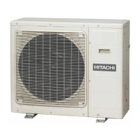
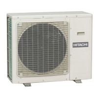
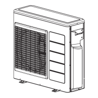
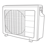
OUTDOOR UNIT
APRIL 2007
Refrigeration & Air-Conditioning Division
SERVICE MANUAL
PM
REFER TO THE FOUNDATION MANUAL
TECHNICAL INFORMATION
FOR SERVICE PERSONNEL ONLY
CONTENTS
SPECIFICATIONS ------------------------------------------------------------------- 5
INSTALLATION --------------------------------------------------------------------- 16
CONSTRUCTION AND DIMENSIONAL DIAGRAM --------------------- 20
WIRING DIAGRAM ---------------------------------------------------------------- 21
MAIN PARTS COMPONENT --------------------------------------------------- 24
CIRCUIT DIAGRAM --------------------------------------------------------------- 25
BLOCK DIAGRAM ----------------------------------------------------------------- 29
BASIC MODE ----------------------------------------------------------------------- 31
REFRIGERATING CYCLE DIAGRAM --------------------------------------- 51
DESCRIPTION OF MAIN CIRCUIT OPERATION ----------------------- 52
TROUBLE SHOOTING ----------------------------------------------------------- 88
PARTS LIST AND DIAGRAM -------------------------------------------------- 94
After installation
(W)
(A)
COOLING CAPACITY
DC INVERTER FIVE SYSTEM MULTI
TYPE
MODEL
POWER SOURCE
TOTAL INPUT
TOTAL AMPERES
SPECIFICATIONS
RAM-90QH5
HEATING CAPACITY
DIMENSIONS (mm)
NET WEIGHT
1ø, 220 - 240V, 50/60Hz
W
H
D
(kg)
(kW)
(B.T.U.)
REFER TO THE SPECIFICATIONS PAGE
OUTDOOR UNIT
RAM-90QH5
RAM-90QH5
950
800
370
71
NOTE:
This manual describes only points that differ from
PM No. 0322E, PM No. 0355E and PM No. 0366E
for items not described in this manual.

Table of Contents

Question and Answer IconNeed help?

Do you have a question about the Hitachi RAM-90QH5 and is the answer not in the manual?

Hitachi RAM-90QH5 Specifications

General IconGeneral
BrandHitachi
ModelRAM-90QH5
CategoryAir Conditioner
LanguageEnglish

Summary

SPECIFICATIONS

SAFETY DURING REPAIR WORK

WORKING STANDARDS FOR PREVENTING BREAKAGE OF SEMICONDUCTORS

FEATURES

NEW REFRIGERANT

Details on the new R410A refrigerant.

NEW TECHNOLOGY

Cautions regarding HFC (R410A) technology.

Refrigerant Piping Materials

Information on refrigerant piping specifications.

Servicing Tools

Tools required for servicing R410A systems.

Air purging by using vacuum pump

Procedure for air purging using a vacuum pump.

INSTALLATION

PIPE LENGTH

Specifications for pipe length.

HIGHT DIFFERENCE

Specifications for height differences.

Connecting the pipe

Steps for connecting refrigerant pipes.

Condensed water disposal of outdoor unit

How to manage condensed water from the outdoor unit.

When Using and Installing in Cold Areas

Installation advice for cold climates.

Connection of the connecting cords and power cord. (Outdoor unit)

Wiring Pattern Indoor Unit

Wiring diagrams for indoor units.

CONSTRUCTION AND DIMENSIONAL DIAGRAM

WIRING DIAGRAM

COMPRESSOR MOTOR

MAIN PARTS COMPONENT

FAN MOTOR

Specifications for the fan motor.

CIRCUIT DIAGRAM

BLOCK DIAGRAM

BASIC MODE

Basic Cooling Operation

Detailed explanation of basic cooling operation.

Cooling Sleep Operation

Operation details for cooling sleep mode.

Cooling Defrost

Procedure for cooling defrost cycle.

Heating Basic Operation

Detailed explanation of basic heating operation.

Heating Sleep Operation

Operation details for heating sleep mode.

Dehumidifying

Dehumidifying Sleep Operation

Operation details for dehumidifying sleep mode.

DEFROST

AUTO-FRESH DEFROST

FORCED COOLING

PROCESSING AT OVERHEAT THERMISTOR (OH) HIGH TEMPERATURE

REFRIGERATING CYCLE DIAGRAM

DESCRIPTION OF MAIN CIRCUIT OPERATION

Power Circuit

Explanation of the main power circuit.

Indoor/Outdoor Interface Circuit

Circuit for communication between indoor and outdoor units.

System power Module Circuit

Explanation of the system power module circuit.

Power Supply Circuit

Details of the power supply circuits.

Reversing valve control circuit

Circuit that controls the reversing valve.

Overload control circuit (OVL control circuit)

Circuit for managing overload conditions.

Reset circuit

Circuit responsible for microcomputer reset.

Temperature Detection Circuit

Circuit for detecting various temperatures.

Electric expansion valve

Operation and control of electric expansion valves.

Power Factor Control Circuit

Circuit for controlling power factor.

INSPECTING OUTDOOR ELECTRICAL PARTS

LED lighting mode

Interpretation of LED indicators for troubleshooting.

Inspection method 1

Step-by-step guide for inspection method 1.

Inspection method 2

Step-by-step guide for inspection method 2.

Inspection method 3

Step-by-step guide for inspection method 3.

HOW TO OPERATE USING THE SERVICE SWITCH THE OUTDOOR UNIT

HOW TO OPERATE THE OUTDOOR UNIT INDEPENDENTLY

Procedure for independent outdoor unit operation.

TROUBLE SHOOTING

PRECAUTIONS FOR CHECKING

Safety precautions before performing checks.

Discharge procedure and how to cut off power to power circuit

Steps for safely discharging capacitors and cutting power.

Lighting mode self-diagnosis lamp

Location and function of self-diagnosis LEDs.

TROUBLESHOOTING OF THE INTELLIGENT POWER MODULE (IPM)

HOW TO CHECK POWER MODULE

Procedure for checking the power module.

PARTS LIST AND DIAGRAM

Related product manuals