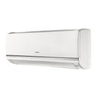
Do you have a question about the Hitachi RAS-12FSXNHE and is the answer not in the manual?
Covers safety warnings, symbols, and precautions related to system operation and installation.
Provides additional safety guidelines regarding electrical hazards, refrigerant leaks, and installation precautions.
Information on the high-pressure vessel and safety device, including warnings against modification.
Refrigerant cycle diagram and component list for RAS-(8-12)FSXN1E.
Refrigerant cycle diagram and component list for RAS-(14/16)FSXN1E.
Refrigerant cycle diagram and component list for RAS-(5/6)FSXNH(E).
Refrigerant cycle diagram and component list for RAS-(8-12)FSXNH(E).
Details on the correct method for lifting units using slings, emphasizing safety and proper attachment points.
Guidance on selecting suitable locations for outdoor units, considering sunlight, ventilation, noise, and access.
Covers foundation requirements and the correct positioning and fastening of anchorage bolts for outdoor units.
Guidelines for selecting the correct refrigerant pipe sizes based on system type and outdoor unit capacity.
Instructions for selecting pipe sizes, with cautions on using incorrect diameters affecting performance and compressor life.
Details on copper pipe specifications, sizes, connection methods, and insulation requirements.
Provides general guidance on installing refrigerant pipes, including flared connection mounting and insulation.
Specifies pipe connection details and sizes for heat pump and heat recovery systems, including kit usage.
Procedure for performing air-tight tests on refrigerant piping, including pressure requirements and leak detection methods.
Detailed procedure for conducting air-tight tests using manifold gauges and nitrogen gas, including pass/fail criteria.
Steps for vacuum pumping refrigerant lines to remove moisture and non-condensable gases.
Methodology for calculating and recording additional refrigerant required based on piping length and system configuration.
Details the calculation process for refrigerant charge based on pipe diameter, length, and unit capacity.
Step-by-step instructions for charging additional refrigerant into the system, including safety precautions and valve operations.
Describes the automatic system for judging the refrigerant amount and interpreting the results.
Step-by-step guide to perform the refrigerant amount check operation using the PCB and DIP switches.
Focuses on preventing and managing refrigerant gas leaks, including critical concentration limits and ventilation.
Safety precautions and regulations regarding refrigerant leaks, including maximum permissible concentrations.
Specifies the maximum permissible concentration of HFC gas R410A in air to prevent suffocation.
Measures to take in case of refrigerant leaks, focusing on room ventilation and air circulation.
Illustrates how to connect power supply circuits for heat pump and heat recovery systems.
Instructions on how to set DIP switches (DSW) on PCB1 for various functions like refrigerant cycle, capacity, and test run.
Instructions for setting up test run and service functions using DSW4 switches.
Details settings for emergency operation, test run, and service using DSW5 switches.
Essential checks to be performed before starting the test run, including wiring, connections, and component settings.
Step-by-step instructions for conducting the test run, including checks for fan rotation, compressor noise, and system operation.
Guide for using the PC-ART remote controller to perform test run operations and check system status.
Instructions for using the PC-ARF remote controller to perform test run operations and check system parameters.
A checklist to verify all critical parameters and operations during the test run.
Explains the devices and combinations used for compressor protection against high pressure and cold starts.
| Cooling Capacity | 3.5 kW |
|---|---|
| Heating Capacity | 4.0 kW |
| Power Supply | 220-240V, 50Hz |
| Energy Efficiency Ratio (EER) | 3.21 |
| Coefficient of Performance (COP) | 3.61 |
| Refrigerant | R32 |
| Indoor Unit Weight | 9.5 kg |
| Noise Level (Outdoor Unit) | 50 dB(A) |
| Type | Split System |


 Loading...