Do you have a question about the Hitachi RAS-16FSN/FXN and is the answer not in the manual?
Immediate hazard that WILL result in severe injury or death.
Hazards or unsafe practices that COULD result in severe personal injuries or death.
Hazards or unsafe practices that COULD result in minor personal injury or product or property damage.
DANGER: Electrical shock, safety device tampering, and access hazards.
Fire safety procedures, grounding, and fuse checks.
DANGER: High pressure vessel safety and protection device information.
DANGER: Do not change high-pressure switch or cut-out value locally.
Supply power 12 hours before start-up for compressor heating.
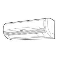
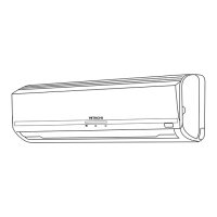
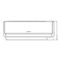
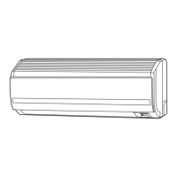
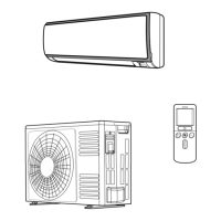
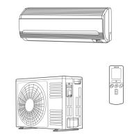
Overview of the PC-P1HE remote control unit and its functions.
Steps to perform before operating the unit for cooling, heating, dry, and fan modes.
Procedures for adjusting temperature, fan speed, and air louver direction.
Steps to set ON/OFF timers using the TIME and ON/OFF TIMER switches.
Indicates RUN blinking, ALARM, power failure, and electric noise.
Three Minute Guard, Automatic Restart after Power Failure.
CAUTION for water leakage and warnings about abnormal smells/smoke.
Check airflow, heat sources, filters, doors/windows, operating range.
Methods and precautions for transporting the outdoor unit.
Guidelines for adequate space around the unit for operation and maintenance.
CAUTION: Use R410A; avoid flammable/poisonous gases for testing.
Procedures for refrigerant piping work on the outdoor unit.
CAUTION on R410A use and dangers of flammable/poisonous gases.
Apply torque for tightening and cautions for spindle valve.
Steps for evacuating the system and charging refrigerant.
Charge refrigerant, open valves, and circulate for 10+ minutes.
Procedure for operating stop valves using a hexagonal wrench.
Limits for HCFC/HFC gas concentration in air (0.44 kg/m³ for R410A).
Procedure to determine and charge additional refrigerant based on piping and units.
General checks and guidelines for electrical wiring installation.
Confirm secure ground wire connection and specified fuse capacity.
WARNINGS/CAUTIONS regarding fan stop, pest protection, wire securing, conduit use, and power switch OFF.
Wiring diagram for connecting power supply and indoor/outdoor units.
Shows connections for power supply, earth, and inter-unit wiring.
Dip switch settings for test operations and service functions.
Settings for emergency compressor operation modes.
Guide to setting outdoor unit dip switches for various functions.
Procedure for setting refrigerant cycle number for H-Link systems.
Wiring instructions for connecting indoor and outdoor units.
Verify terminal correctness and follow codes to prevent damage.
Caution regarding incorrect operating line connection causing PCB failure.
Step-by-step guide for performing test run using the remote control switch.
Procedure for performing test run directly from the outdoor unit side using DIP switches.
Procedure to turn on power and set the unit to TEST RUN mode.
Guide to setting DSW4 DIP switch for service operations.
Explanation of DSW4 settings for test run, compressor, and defrost.
Alarms related to transmission failure between indoor unit and remote control.
Instructions for noting alarm codes and contacting service.
Table listing alarm codes, their content, and leading causes.
| Brand | Hitachi |
|---|---|
| Model | RAS-16FSN/FXN |
| Category | Air Conditioner |
| Language | English |