EasyManua.ls Logo

Hitachi RAS-35FH6 User Manual

Hitachi RAS-35FH6
96 pages
To Next Page IconTo Next Page
Page #1 background imageLoading...
Page #1 background image
NO. 0025E
SPECIFICATIONS AND PARTS ARE SUBJECT TO CHANGE FOR IMPROVEMENT
ROOM AIR CONDITIONER
INDOOR UNIT + OUTDOOR UNIT
SERVICE MANUAL
AW
REFER TO THE FOUNDATION MANUAL
TECHNICAL INFORMATION
FOR SERVICE PERSONNEL ONLY
(W)
(A)
(kW)
(B.T.U./h)
(W)
(A)
(kW)
(B.T.U./h)
W
H
D
(kg)
DC INVERTER (WALL TYPE)
TYPE
MODEL
POWER SOURCE
TOTAL INPUT
TOTAL AMPERES
CAPACITY
TOTAL INPUT
TOTAL AMPERES
CAPACITY
DIMENSIONS
(mm)
NET WEIGHT
SPECIFICATIONS
RAS-35FH6
CONTENTS
SPECIFICATIONS ------------------------------------------------------------------- 4
HOW TO USE ----------------------------------------------------------------------- 5
CONSTRUCTION AND DIMENSIONAL DIAGRAM --------------------- 15
MAIN PARTS COMPONENT --------------------------------------------------- 17
WIRING DIAGRAM ---------------------------------------------------------------- 19
CIRCUIT DIAGRAM --------------------------------------------------------------- 20
BLOCK DIAGRAM ----------------------------------------------------------------- 22
BASIC MODE ----------------------------------------------------------------------- 23
REFRIGERATING CYCLE DIAGRAM --------------------------------------- 29
DESCRIPTION OF MAIN CIRCUIT OPERATION ----------------------- 30
SERVICE CALL Q & A ---------------------------------------------------------- 58
TROUBLE SHOOTING ----------------------------------------------------------- 61
Procedure for Disassembly and Reassembly 88
PARTS LIST AND DIAGRAM -------------------------------------------------- 90
RAS-35FH6/RAC-35YH6
RAC-35YH6
COOLING
HEATING
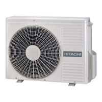
OUTDOOR UNIT
INDOOR UNIT
780
280
220
9.5
548
35
1 PHASE, 50 Hz, 220-230V
1,090 (155 ~ 1,460)
5.22-4.99
3.50 (0.90 ~ 4.00)
11,940 (3,070 ~ 13,650)
1,110(115 ~ 1,440)
5.32-5.09
4.20 (0.90 ~ 5.00)
14,330 (3,070 ~ 17,060)
After installation
RAS-35FH6 RAC-35YH6
750 (+91)
288 (+47)
FEBRUARY 2008 Hitachi Household Appliances(Wuhu) Co.,Ltd.
08A392_01_RAS_35FH6_cover_E 2008.3.7, 17:451

Table of Contents

Question and Answer IconNeed help?

Do you have a question about the Hitachi RAS-35FH6 and is the answer not in the manual?

Hitachi RAS-35FH6 Specifications

General IconGeneral
BrandHitachi
ModelRAS-35FH6
CategoryAir Conditioner
LanguageEnglish

Summary

Safety During Repair Work

Safety During Repair Work

Crucial safety instructions for personnel before and during repair operations.

Semiconductor Handling Standards

Handling Precautions

Specific procedures and precautions for handling semiconductors.

How to Use the Air Conditioner

Safety Precautions

Crucial safety warnings and prohibitions for unit operation.

Precautions During Installation

Safety guidelines for installing the air conditioner unit properly.

Precautions During Operation

Safety measures to follow during normal operation of the unit.

Precautions During Shifting or Maintenance

Safety advice for performing maintenance or shifting the unit.

Unit Maintenance Procedures

Air Filter Cleaning

Steps for cleaning the air filter to maintain performance.

System Information and Service

Regular Inspection Guidelines

Recommended inspection points for periodic checks.

Key Component Specifications

Wiring Diagram

Wiring Diagram

Electrical wiring schematic for the indoor and outdoor units.

Circuit Diagrams

Circuit Diagram

Detailed schematic of the unit's electronic circuits.

System Block Diagram

Block Diagram

Functional overview of the unit's system architecture and component connections.

Refrigeration Cycle Diagram

Refrigeration Cycle Diagram

Diagram illustrating the refrigerant flow for cooling, heating, and defrosting.

Main Circuit Operation Explained

Outdoor Unit Electrical Systems

Outdoor Unit Power Circuit Operation

Explanation of how the outdoor unit converts AC to DC power.

Indoor/Outdoor Unit Communication

Intelligent Power Module (IPM) Diagnosis

Printed Wiring Board Power Circuits

Power Circuit Troubleshooting

Steps to identify and resolve power circuit issues based on voltage checks.

Microcomputer Peripheral Circuitry

Overload Control Circuit Function

How the system prevents overload by controlling compressor speed.

Troubleshooting Common Issues (Q&A)

General Troubleshooting Precautions

General Troubleshooting Precautions

Safety warnings and essential checks before troubleshooting the unit.

Power Circuit Discharge Procedure

Power Circuit Discharge Procedure

Safe method for discharging capacitors in the power circuit before servicing.

Failure Diagnosis Support Functions

Interpreting Failure Indicators

Understanding how the timer lamp and LD301 indicate unit failures.

Troubleshooting Timer Lamp Blinks

Self-Diagnosis Lighting Mode Mapping

Mapping blinking patterns to specific failure causes and possible solutions.

Outdoor Unit Troubleshooting Flow

Compressor Connector and Self-Diagnosis Check

Checking the compressor connector and self-diagnosis lamp status.

Unit Electrical and Refrigeration Checks

Indoor Lamp, Compressor, and Refrigeration Checks

Diagnosing issues based on the indoor timer lamp, compressor status, and refrigeration cycle.

Indoor Unit Electrical Part Troubleshooting

Power Supply and Control Voltage Verification

Verifying power supply and control voltages for the indoor unit.

Control P.W.B. (Power Circuit) Diagnostics

Detailed checks on the control P.W.B. power circuit, including voltage and component integrity.

Remote Controller Troubleshooting

Outdoor Unit Servicing Precautions

Outdoor Unit Electrical Part Diagnostics

Connection, Voltage, and Cable Checks

Verifying cable connections and voltage outputs for outdoor unit operation.

Power Supply and Fault Indicator Interpretation

Checking power supply voltage and interpreting self-diagnosis lamp (LD301) codes.

Communication Error Troubleshooting Steps

Diagnosing and resolving communication errors between indoor and outdoor units.

Thermistor Error Diagnostics

Troubleshooting thermistor errors indicated by LD301 blinking codes.

OH Thermistor and Overload Cut Troubleshooting

Diagnosing OH thermistor issues and overload protection trips.

Outdoor Unit Service Switch Operation

Outdoor Unit Service Switch Operation

How to use the service switch for forced cooling mode operation.

Intelligent Power Module (IPM) Diagnosis Methods

IPM Diagnosis Methods

Methods for diagnosing the Intelligent Power Module using a multimeter.

Indoor Unit Disassembly and Reassembly

Related product manuals