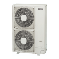
Do you have a question about the Hitachi RAS-3HVRNS3 and is the answer not in the manual?
Copyright, usage restrictions, product updates, and disclaimer on printing errors.
Highlights use of R410A refrigerant and adherence to RoHS regulations for eco-friendly operation.
Explains DANGER, CAUTION, and NOTE symbols for safety instructions during operation and installation.
Crucial safety warnings on electrical hazards, unit adjustments, fire procedures, and general precautions.
Details model coding for IVX outdoor units: series, HP, phase, and refrigerant type.
Explains model coding for ES outdoor units: series, HP, phase, and refrigerant type.
Covers DANGER (Pressure Vessel), CAUTION (EMC), and general safety checks for start-up, operation, and maintenance.
Details operating temperature ranges and maximum allowable pressure/cut-out values for system operation.
Details maximum piping length (Lo-i) and height difference (Ho-i) for indoor/outdoor unit connections.
Lists gross weight for outdoor unit models: RAS-(2-2.5)HVNP1, RAS-3HVNC1, RAS-3HVRNS3.
Important pre-operation steps: power supply duration, compressor oil warming, checking outdoor unit condition.
Details automatic controls: compressor guard, frost prevention, auto restart, defrost, overload prevention, hot start.
Covers immediate actions, normal sounds, no operation, poor cooling/heating, and abnormal louvers.
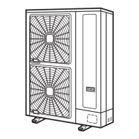
Illustrates and lists outdoor unit parts (1-10, 11-19) for identification, referencing technical catalogue.
Diagram of refrigerant flow with numbered components (1-8, 9-15) for cooling and heating operations.
Guidelines for transporting and installing outdoor units: clearance, ventilation, and environmental considerations.
Illustrations showing required clearance for various single and multiple unit installation configurations.
Guidance on selecting installation locations to mitigate effects of strong winds on unit operation.
Details optional parts for airflow management and protection: guides, guards, and hoods.
Instructions for securing unit with anchor bolts and providing adequate drainage around the foundation.
Guidance on foundation installation, vibration mats, and metal plates for frame width adjustment.
Instructions for refrigerant piping materials, preparation, and insulation to ensure system performance.
Selection criteria for copper pipes: thickness, material, and cleanliness for pressure strength.
Guidelines for suspending piping to prevent contact with building parts and avoid abnormal sounds.
Instructions for brazing, emphasizing nitrogen gas use and correct pressure settings.
Procedures for operating stop valves and tightening torque specifications for outdoor unit connections.
Specifies wrench sizes for valves and details piping length limits and system configurations (1 & 2 indoor units).
Guidelines for selecting piping sizes and connecting flare adapters for indoor and outdoor units.
Warnings on refrigerant handling and detailed steps for system evacuation and refrigerant charging.
Table for refrigerant quantity and method for calculating additional charge based on piping length, including DSW setting.
Instructions for installing drain boss/piping for outdoor unit drainage, with notes on cold areas.
Checks for components, EMC, power supply, and critical safety warnings for wiring work.
Diagrams showing electrical wiring connections for outdoor units: power supply and control cables.
Details DIP switch functions (DSW1-DSW6) for test run, functions, refrigerant cycle, and multiple unit settings.
Guidelines for connecting electrical wires between indoor/outdoor units: wire types and grounding.
Warnings on incorrect connections, field wiring compliance, and potential PCB failure.
Recommends wire sizes for cables and lists main switch protection requirements (MC, CB, ELB).
Introduces H-LINK system: features, specs, examples, and PCB dip switch settings.
Detailed DIP switch configurations for outdoor/indoor units in multiple H-LINK system setups.
Refers to specific manuals for PC-ART and PC-ARF remote control switch installations.
Safety precautions before test run: check resistance, stop valves, compressor oil warming, avoid touching parts.
Step-by-step guide for test run via remote control: check connections, indicators, and troubleshoot wrong portions.
Troubleshooting for lamp flickering and alarm codes related to wiring and unit status.
Procedure for outdoor unit test run via DIP switch settings (DSW301).
Setting DSW301 for Cooling/Heating test run, starting test run, and manual compressor OFF.
Procedure to start manual defrost operation and notes on its availability and limitations.
Details compressor protection (high pressure switch) and fan motor protection mechanisms and settings.
Information on control circuit components: fuse, CCP timer, and internal thermostat settings.
Guide to understanding alarm code indications on the remote control switch for various models.
| Brand | Hitachi |
|---|---|
| Model | RAS-3HVRNS3 |
| Category | Air Conditioner |
| Language | English |


