EasyManua.ls Logo

Hitachi RAS-4HVRNME-AF - User Manual

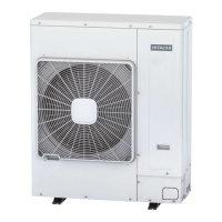
Hitachi RAS-4HVRNME-AF
40 pages
To Next Page IconTo Next Page
Loading...
INSTALLATION AND OPERATION MANUAL
YUTAKI S/S80 Series
RAS-(3-6)H(V)RNME-AF
Outdoor Unit
PMML0205A rev.4 - 11/2012 Printed in Spain
PMML0205A rev.4 - 11/2012
YUTAKI S/S80 SERIES - OUTDOOR UNIT

Other manuals for Hitachi RAS-4HVRNME-AF

Questions and Answers:

Hitachi RAS-4HVRNME-AF Specifications

General IconGeneral
Cooling Capacity4.0 kW
RefrigerantR32
Power Supply220-240V, 50Hz
TypeSplit
Outdoor Unit Dimensions (HxWxD)780 mm

Summary

PART I - OPERATION

SAFETY SUMMARY

Overview of safety precautions and warnings, including DANGER, WARNING, CAUTION.

IMPORTANT NOTICE

Details on system compatibility, manual usage, and policy.

SYSTEM DESCRIPTION

Maximum Allowable Pressure and High Pressure Cut-out Value

Specifies pressure limits and safety cut-out values for the system.

DANGER: Pressure Vessel and Safety Device

Highlights risks associated with pressure vessels and safety devices.

BEFORE OPERATION

CAUTION

Pre-operation checks and precautions for compressor and system.

AUTOMATIC CONTROLS

Compressor Protection Features

Includes 3-minute guard and auto restart after power failure.

Operation Mode Controls

Covers frost prevention, slow air control, and hot start during heating.

Defrosting and Overload Prevention

Details automatic defrosting cycle and overload prevention.

BASIC TROUBLESHOOTING

CAUTION

Immediate actions for smells or white smoke from the unit.

THIS IS NOT ABNORMAL

Describes normal sounds and steam generation.

NO OPERATION

Troubleshooting steps for no operation.

NOT COOLING WELL OR HEATING WELL

Checks for common cooling/heating performance issues.

IF TROUBLE STILL REMAINS...

Information to provide to service contractor.

NAME OF PARTS

OUTDOOR UNIT (Example of RAS-5 H(V)RNME-AF)

Identifies components of the outdoor unit with diagrams.

REFRIGERANT CYCLE

EXAMPLE:

Diagram illustrating the refrigerant flow and components.

UNITS INSTALLATION

OUTDOOR UNITS INSTALLATION

Guidelines for installing outdoor units safely and effectively.

INSTALLATION SPACE - INLET & UPPER CLEARANCES

Single Installation - Blocked in Inlet Side

Clearance requirements for single units with blocked inlets.

Multiple Installation - Blocked in Inlet Side

Clearances for multiple units with blocked inlets.

Single Installation - Upper Side Open

Clearance requirements for single units with open upper side.

Multiple Installation - Upper Side Open

Clearances for multiple units with open upper side.

Single Installation - Upper Side Blocked

Clearance requirements for single units with blocked upper side.

Multiple Installation - Upper Side Blocked

Clearances for multiple units with blocked upper side.

INSTALLATION SPACE - OUTLET & LATERAL CLEARANCES

Outlet Side Blocked - Single Installation

Clearance for single units with blocked outlet side.

Outlet Side Blocked - Multiple Installation

Clearances for multiple units with blocked outlet side.

Lateral Side Blocked - Single Installation

Clearance for single units with blocked lateral side.

INSTALLATION SPACE - STACKING & ROW CONFIGURATIONS

Stack Installation (Single & Multiple)

Clearance for stacking units vertically, single or multiple.

Multiple Rows Installation

Clearance for units installed in multiple rows.

INSTALLATION PLACE PROVISION

Concrete Foundation

Requirements for concrete foundation and base installation.

REFRIGERANT PIPING & REFRIGERANT CHARGE

Fix Unit to the wall

Instructions for wall mounting the outdoor unit.

Suspended unit

Guidelines for suspending the outdoor unit.

Installing location where the unit will be exposed to strong wind

Recommendations for installing units in windy locations.

PIPING MATERIALS

Details on selecting and preparing copper pipes for the system.

REFRIGERANT PIPING & REFRIGERANT CHARGE

SUSPENSION OF REFRIGERANT PIPING

Methods for suspending refrigerant piping to prevent damage.

PIPING CONNECTION FOR OUTDOOR UNIT

Procedure for connecting pipes to the outdoor unit from different directions.

REFRIGERANT PIPING & REFRIGERANT CHARGE

Mount the piping cover

Instructions for mounting piping cover to prevent water entry.

Tightening torque

Specifications for tightening torque of pipe connections.

REFRIGERANT PIPING LENGHT

Chart for determining piping length based on height difference.

Setting of Pipe Length DSW

Procedure for setting pipe length using DSW2.

REFRIGERANT PIPING & REFRIGERANT CHARGE

REFRIGERANT PIPING SIZE

Specifications for gas and liquid pipe sizes for indoor/outdoor units.

BRAZING WORK

Guidelines and precautions for pipe brazing with nitrogen gas.

CAUTION OF THE PRESSURE BY CHECK JOINT

Procedure for pressure measurement using check joints.

REFRIGERANT CHARGE AND VACUUM PROCEDURE

CAUTION

Warnings regarding charging gases and potential hazards.

REFRIGERANT CHARGING QUANTITY

Table of factory refrigerant charge amounts and pipe lengths.

PUMP DOWN REFRIGERANT

Procedure for collecting refrigerant for relocation.

DRAIN PIPING

DRAIN DISCHARGING BOSS

Description and connection procedure for the drain boss.

NOTE

Important notes regarding drain boss usage in cold areas.

ELECTRICAL WIRING

GENERAL CHECK

General checks for electrical components and compliance.

CAUTION

Precautions for wiring terminal blocks and electrical parts.

DANGER

Safety warning about connecting/adjusting wiring with power off.

ELECTRICAL WIRING

ELECTRICAL WIRING CONNECTION FOR OUTDOOR UNITS

Diagrams for electrical wiring connections to outdoor units.

SETTING OF DIP SWITCHES FOR OUTDOOR UNIT

Details on the location and types of DIP switches on the PCB.

ELECTRICAL WIRING

COMMON WIRING

General wiring practices and compliance with local codes.

ELECTRICAL WIRING BETWEEN INDOOR UNIT AND OUTDOOR UNIT

Instructions for wiring between indoor and outdoor units.

CAUTION

Attention to operating line connection for correct PCB function.

ELECTRICAL WIRING

WIRE SIZE

Recommended minimum wire sizes for field-provided wires.

TEST RUN

PRELIMINARY CHECK

Checks before performing the test run.

CHECKING THE UNIT

Visual inspection of the unit for damage and installation status.

ELECTRICAL CHECKING

Checks related to electrical resistance and connections.

CHECKING THE REFRIGERANT CIRCUIT

Verification of stop valves, piping, and refrigerant charge.

CAUTION

Warning not to operate until all checks are cleared.

TEST RUN PROCEDURE FROM INDOOR UNIT SIDE

Configuration for outdoor unit test run

Procedure to configure and start the test run from the remote control.

TEST RUN FROM OUTDOOR UNIT SIDE

DIP Switch Settings for Test Run

Explains DSW1 settings for test run, operation mode, and compressor control.

Manual Defrost Operation Procedure

Procedure for manually initiating and ending defrost operation.

Operation Warnings

Warnings about touching PCB and service covers during operation.

SAFETY SUMMARY & CONTROL DEVICE SETTING

Compressor Protection

Details on high pressure switch and control circuit fuses.

Fan Motor Protection

Explanation of fan motor output reduction based on thermistor temperature.

TROUBLESHOOTING

Alarm Code Indication of Remote Control Switch

Overview of alarm codes displayed on the remote control.

TROUBLESHOOTING

Alarm Codes and Main Factors (Part 1)

Troubleshooting table for various alarm codes and their causes.

TROUBLESHOOTING

Alarm Codes and Main Factors (Part 2)

Troubleshooting table for various alarm codes and their causes.

Related product manuals