EasyManua.ls Logo

Hitachi RAS-4HVRNS3E - User Manual

Hitachi RAS-4HVRNS3E
50 pages
To Next Page IconTo Next Page
Loading...
UTOPIA IVX PREMIUM / IVX STANDARD Series
RAS-(3-10)H(V)NP(1)E / RAS-(8-10)HNCE
UTOPIA ES Series
RAS-4H(V)RNS3E
INSTALLATION AND OPERATION MANUAL

Questions and Answers:

Hitachi RAS-4HVRNS3E Specifications

General IconGeneral
BrandHitachi
ModelRAS-4HVRNS3E
CategoryAir Conditioner
LanguageEnglish

Summary

2 SAFETY

2.1 APPLIED SYMBOLS

Explanation of safety symbols (DANGER, CAUTION, NOTE) used in the manual.

3 PRODUCT GUIDE

3.1 CLASSIFICATION OF IVX OUTDOOR UNITS MODELS

Model coding for HITACHI IVX outdoor units.

3.2 CLASSIFICATION OF ES OUTDOOR UNITS MODELS

Model coding for HITACHI ES outdoor units.

4 IMPORTANT NOTICE

Allowable Pressure and Cut-out Values

Specifies maximum allowable pressure and high pressure cut-out values for safety.

5 TRANSPORTATION AND HANDLING

9 BASIC TROUBLESHOOTING

10 NAME OF PARTS

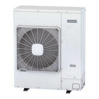
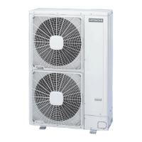
10.1 Example of RAS-3 HVNP1 E; RAS-4 H(V)RNS3 E

Diagram and list of parts for specific outdoor unit models.

11 REFRIGERANT CYCLE

Example of RAS-4 H(V)NP1 E

Refrigerant cycle diagram for RAS-4H(V)NP1E outdoor unit.

Example of RAS-4 H(V)RNS3 E

Refrigerant cycle diagram for RAS-4H(V)RNS3E outdoor unit.

12 UNITS INSTALLATION

12.1 OUTDOOR UNITS INSTALLATION

Guidelines for installing outdoor units, including safety and clearance.

12.1.1 Installation Space Requirements

Diagrams showing required installation space for single and multiple units.

13 REFRIGERANT PIPING & REFRIGERANT CHARGE

13.1 PIPING MATERIALS

Requirements for copper pipes, including thickness, cleanliness, and handling.

13.2 SUSPENSION OF REFRIGERANT PIPING

Methods for suspending refrigerant piping to prevent vibration damage.

13.3 PIPING CONNECTION FOR OUTDOOR UNIT

Refrigerant Evacuation and Charging

13.4 REFRIGERANT PIPING LENGTH

Piping Length Specification for Header Branch

Specifications for refrigerant piping length in header branch systems.

13.4.4 Refrigerant Charge

13.6 REFRIGERANT CHARGING QUANTITY

15 ELECTRICAL WIRING

15.2 ELECTRICAL WIRING CONNECTION FOR OUTDOOR UNITS

15.3 COMMON WIRING

15.3.3 H-LINK II System

15.3.4 System Installation DIP Switch Setting

16 TEST RUNNING

16.1 TEST RUN PROCEDURE BY REMOTE CONTROL SWITCH

16.2 TEST RUN FROM OUTDOOR UNIT SIDE

17 SAFETY SUMMARY & CONTROL DEVICE SETTING

Compressor Protection Features

Explanation of high pressure switch and cut-out values for compressor protection.

Fan Motor Protection Features

How thermistor settings protect the fan motor from overheating.

18 TROUBLESHOOTING

Related product manuals