Do you have a question about the Hitachi RAS-7HVRNM2 and is the answer not in the manual?
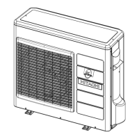
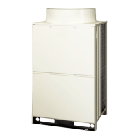
Identifies and lists all parts of the outdoor unit with corresponding numbers and diagrams.
Provides a comprehensive list of tools and instruments required for proper installation.
Guides the process of selecting the appropriate outdoor and indoor unit models based on capacity.
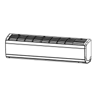
Explains how to select indoor units for systems connected to a single outdoor unit.
Lists compatible combinations of specific outdoor and indoor unit models.
Details advanced rules for combining outdoor and indoor units beyond standard configurations.
Lists and describes the accessories included with the outdoor unit for installation.
Details essential checks to perform before installing the outdoor unit, covering location and conditions.
Specifies the required clearances around the outdoor unit for operation and maintenance.
Explains the proper methods for securing the outdoor unit to its foundation using anchor bolts.
Details the types of pipes and materials required for refrigerant lines and their preparation.
Explains the correct procedure and specifications for flaring refrigerant pipes and making joints.
Guides the selection of appropriate pipe sizes based on unit capacity and piping length.
Illustrates how to connect refrigerant pipes, including stop valve positions and directions.
Details the process of connecting refrigerant pipes and tightening flare nuts to prevent leaks.
Covers essential checks for electrical components, power supply, and grounding before wiring.
Shows how to connect power and control cables to the outdoor unit and between units.
Specifies minimum wire sizes for power source connections based on European standards.
Configuration of unit numbers and refrigerant cycle for communication systems.
Assigns refrigerant cycle identification numbers for multiple unit systems.
Adjusts terminal resistance settings for H-LINK systems with multiple outdoor units.
Configures the dip switch for simultaneous operation of multiple indoor units.
Details the integration of the unit with Demand Response Enabling Devices (DRED).
Describes methods for performing leak tests on the refrigerant piping system.
Details the process of evacuating the system and charging the correct amount of refrigerant.
Provides formulas and tables for calculating the required additional refrigerant quantity.
Lists crucial checks and preparations required before starting the unit's test run.
Details the step-by-step process for conducting the operational test run and verifying system performance.
Explains how to configure optional operating functions using the dip switch settings.
Describes the procedure for setting up external input and output signals for unit control.
| Category | Air Conditioner |
|---|---|
| Type | Split System |
| Cooling Capacity | 2.0 kW |
| Heating Capacity | 2.5 kW |
| Refrigerant | R32 |
| Power Supply | 220-240V, 50Hz |
| Outdoor Unit Noise Level | 48 dB |