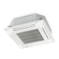
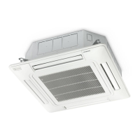
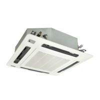
This document is the Installation and Operation Manual for Hitachi Indoor Units, specifically the System Free 4-way cassette models RCI-(1.0-6.0)FSR1, designed for cooling and heating applications.
Function Description
The Hitachi RCI-(1.0-6.0)FSR1 indoor unit is a 4-way cassette type air conditioning unit designed for use in System Free configurations. It provides both cooling and heating functionalities, ensuring comfortable indoor environments. The unit is controlled via a remote controller, allowing users to adjust various settings such as fan speed, circulation function, motion sensor operation, filter indication interval, and individual louver settings.
Important Technical Specifications
Model Classification
The indoor unit models are classified as RCI-(1.0-6.0)FSR1, where:
- RCI: Indicates the unit type (indoor unit).
- (1.0-6.0): Represents the capacity in HP (Horsepower), ranging from 1.0 HP to 6.0 HP.
- FS: Denotes "SYSTEM FREE."
- R: Indicates the refrigerant type, R32/R410A.
- 1: Represents the series number.
Piping Connections
Refrigerant Piping:
- Piping Position:
- Gas pipe connection: 95 mm (from unit edge) for RCI-(1.0-2.0)FSR1, 140 mm (from unit edge) for RCI-(2.5-6.0)FSR1.
- Liquid pipe connection: 160 mm (from unit edge) for RCI-(1.0-2.0)FSR1, 157 mm (from unit edge) for RCI-(2.5-6.0)FSR1.
- Size of Piping Connection (mm):
- RCI-(1.0-2.0)FSR1:
- Liquid piping: Ø 6.35 (1/4)
- Gas piping: Ø 12.70 (1/2)
- RCI-(2.5-6.0)FSR1:
- Liquid piping: Ø 9.52 (3/8)
- Gas piping: Ø 15.88 (5/8)
- Thickness of Copper Pipes (mm):
- Ø (in) | Ø (mm) | Thickness (mm)
- 1/4 | 6.35 | 0.80
- 3/8 | 9.53 | 0.80
- 1/2 | 12.70 | 0.80
- 5/8 | 15.88 | 1.00
- Flare Pipe Dimensions (mm):
- Ø (in) | Ø (mm) | A +0/-0.4 (mm)
- 1/4 | 6.35 | 9.1
- 3/8 | 9.52 | 13.2
- 1/2 | 12.70 | 16.6
- 5/8 | 15.88 | 19.7
- Flare Nut Dimensions (mm):
- Nominal diameter (in) | Nominal diameter (mm) | B (mm)
- 1/4 | 6.35 | 17
- 3/8 | 9.53 | 22
- 1/2 | 12.70 | 26
- 5/8 | 15.88 | 29
Drain Piping:
- The drain piping must be performed with a down-slope pitch of 1/25 to 1/100.
- The total length of the drain piping (a+b+c) should be ≤ 1100mm.
- Max. 300mm for hose band (accessory) and support part.
- Max. 1.5m for support part.
- Use vinyl chloride pipe (VP25) for drain hose connection.
- Tightening torque for hose band (accessory): 3.0 - 3.5 N·m.
Electrical Wiring
- Power source cable: 0.75 mm² (1~ 230V 50Hz), Max. current: 5 A.
- H-Link transmission wiring: 0.75 mm².
- Terminal board (white): DC 5V.
- Terminal board (black): 1~ 230V 50Hz.
- Circuit Fuse Capacity: 5 A for RCI-(1.0-6.0)FSR1.
- Freeze Protection Thermostat: Cut-Out 0°C, Cut-In 14°C.
- Thermostat Differential: 2°C.
Unit Dimensions
- RCI-(1.0-2.5)FSR1: Cover for Corner Pocket (C) is 248 mm.
- RCI-(3.0-6.0)FSR1: Cover for Corner Pocket (C) is 298 mm.
- Overall unit width: 950 mm.
- Overall unit depth: 950 mm.
- Unit height in False Ceiling (A):
- RCI-1.0 to 2.5HP: 248 mm
- RCI-3.0 to 6.0HP: 298 mm
Installation Clearances
- Service Access Door: ≥1500 mm.
- Piping Connection: ≥1500 mm.
- Drain Piping Connection: ≥1500 mm.
- Ceiling Clearance: 10-20mm.
- Minimum height from floor level: 2.5 meters.
- Recommended installation height: Between 2.5 and 3 meters from the floor level. If the unit is installed higher than 3 meters, a fan is recommended to obtain uniform air temperature.
Motion Sensor Kit PS-MSK2 (Optional)
- Installation Height of Indoor Unit H (m):
- 2.7 m: Sensing Area for Motion Sensor ØA (m) approx. 7.0.
- 3.2 m: Sensing Area for Motion Sensor ØA (m) approx. 8.8.
- Motion Detection: Human Motion.
- The motion sensor is not effective if installed in a high ceiling (higher than 4m).
Usage Features
Remote Controller Operation
The unit is operated via a remote controller (PC-ARFP(1)E recommended). Key functions include:
-
High Speed Setting Function:
- This function adjusts the air flow volume higher than normal air flow volume steps, particularly useful for high ceiling installations.
- Ceiling Height | Setting of remote control switch
-
Below 2.7m | Standard
-
2.7 to 3.0m | High Speed (1)
-
3.0 to 3.5m | High Speed (2)
- 4.0 to 6.0HP:
-
Below 3.2m | Standard
-
3.2 to 3.6m | High Speed (1)
-
3.6 to 4.2m | High Speed (2)
-
Circulation Function at Heating Thermo-Off:
- Maintains fan operation during heating thermo-off to improve temperature distribution at high ceiling sites.
-
Motion Sensor Function (Optional, with kit PS-MSK2):
- Detects human activity and adjusts air conditioning settings (set temperature, air flow volume, and air flow direction) automatically.
- Operation after motion sensor detects absence can be selected from "Running," "Stand-by," or "Stop" on the remote control switch.
- Settings:
- Setting Temperature: Temperature is adjusted 1°C or 2°C for saving capacity.
- Air Flow Volume: The air flow volume is adjusted to lower one volume or to "Slo" (except during dry operation).
- Air Flow Direction: The air flow direction is adjusted to horizontal.
-
Setting the Filter Indication Interval:
- The filter interval indication on the remote control switch can be set in several intervals.
-
Individual Louver Setting:
- Individual control setting for each louver is available with PC-ARFP(1)E remote control.
DIP Switch Settings
DIP switches on the PCB allow for configuration of various unit parameters:
-
DSW3: Capacity Code Setting:
- Used to set the capacity code corresponding to the Horse Power of the indoor unit. Settings are provided for 1.0 HP, 1.5 HP, 2.0 HP, 2.5 HP, 3.0 HP, 4.0 HP, 5.0 HP, and 6.0 HP.
-
DSW4: Unit Model Code Setting:
- Used to set the model code corresponding to the indoor unit type.
-
DSW5 and RSW1: Refrigerant Cycle Number Setting:
- Used to set the refrigerant cycle number, up to 63. Example setting for "Ex. Setting 5 system" shows DSW5 all pins OFF and RSW1 fixed to 5.
-
DSW6 and RSW2: Unit Number Setting:
- Used to set the unit number, up to 63. Example setting for "Ex. Setting n°15" shows DSW6 No 1 PIN is on and RSW2 fixed to 5.
-
DSW7: Fuse Recover:
- In case of applying high voltage to terminal 1,2 of TB2, the fuse (0.5) on the PCB is cut. In such a case, correctly wire to TB2 and then turn ON #1 (as showing beside).
-
DSW9:
- Factory setting.
- Installation of air panel: Silent Iconic.
Maintenance Features
Filter Maintenance
Safety and Control Device Setting
- Freeze Protection Thermostat:
- Cut-Out: 0°C
- Cut-In: 14°C
- Thermostat Differential: 2°C
General Maintenance Notes
- Regular inspections of unit parts or systems are recommended.
- Ensure the air in the room is renewed and the room ventilated every 3 or 4 hours.
- The system fitter and specialist shall provide anti-leak safety in accordance with local regulations.
- The installer and system specialist shall secure safety against the refrigerant leakage according to local regulations or standards (ISO149, ISO5149, EN378, JIS B8610).
- Electrical wiring must comply with national and local regulations.
- Do not install the unit in places where oil is present (including oil for machinery), high concentration of sulphurous gas, flammable gases, saline, acidic or alkaline atmosphere.
- Do not install the unit in places where silicon gas is present, as it can deposit on the heat exchanger and repel water, potentially causing leaks or electrical faults.
- Do not install the unit in a place where the current of expelled air directly affects animals or plants.

 Need help?
 General






 To Next Page
