7.3.4 Considerations
• The dimensions considered in the gures include the space nec-
essary for typical installation, and maintenance work for oper-
ation in refrigeration mode at an outdoor temperature of 35 °C.
If the outdoor temperature is higher and if there is a possibility
of a short circuit between the inlet and outlet air, locate the
most suitable dimensions by calculating the air ow current in
comparison with the dimensions given.
• For installation in several groups, a maximum of six units (A)
one metre apart can be grouped.
• If the unit is surrounded by walls on all four sides, keep one of
the walls partially open.
• Keep the upper side open to prevent mutual interference of
inlet and outlet air for each outdoor unit.
7.4 FOUNDATION AND ANCHORAGE OF OUTDOOR UNIT
7.4.1 Foundations
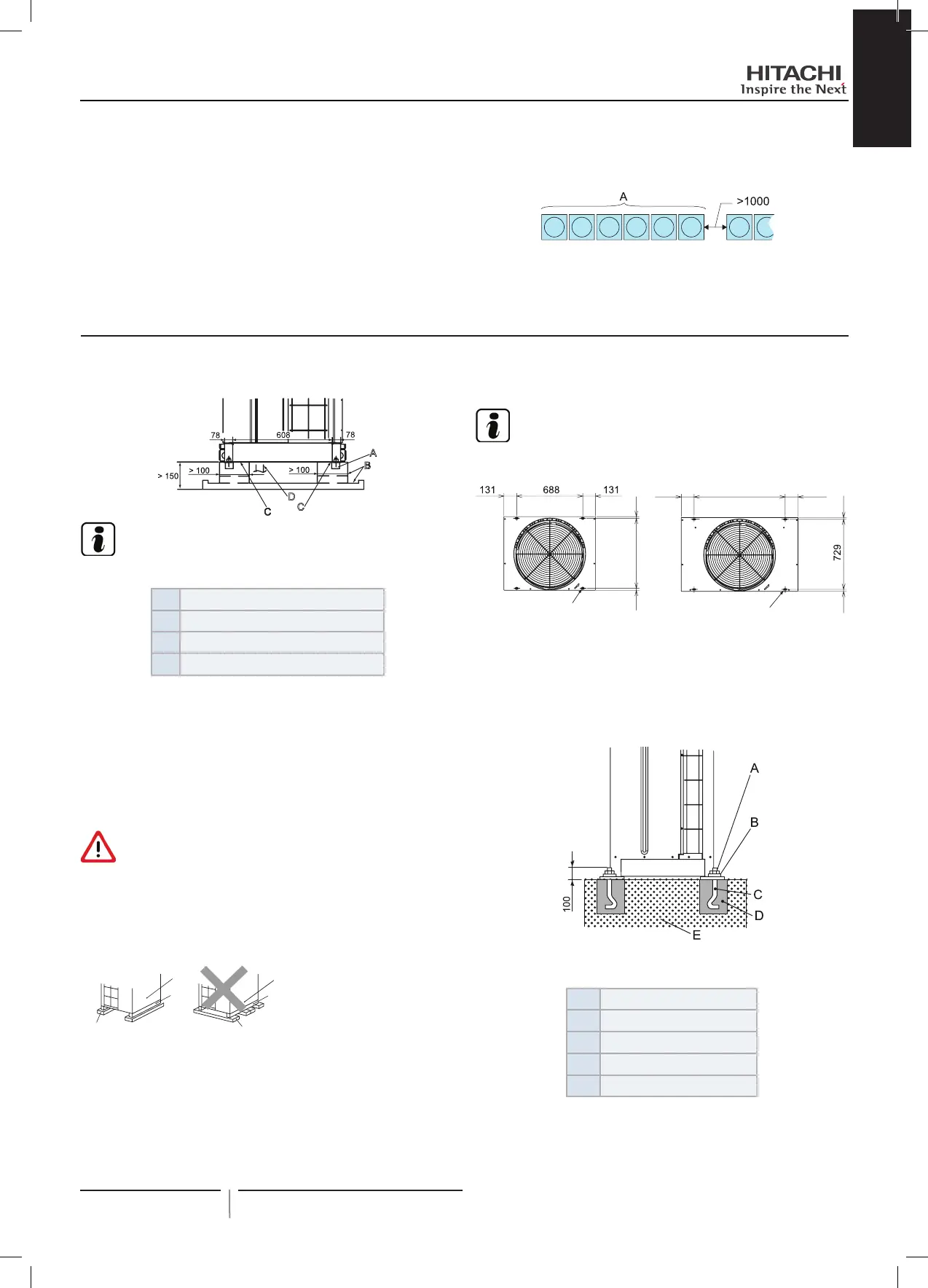
NOTE
All measurements are in mm.
A
Mortar housing ø100x150
B
Drainage 100x20
C
Anti-vibration insulation material
D
Refrigerant pipes
The foundations for the installation of the outdoor unit must be
more than 150 mm above ground level.
The foundations require perimeter drainage to help drain con-
densation.
When a system of condensation drainage pipes is required for
the outdoor unit, the genuine accessory DBS-TP10A should be
used. Do not t drainage pipes or collection trays in cold climates,
as they could freeze and break.
DANGER
Drainage must not take place in areas frequented by pedes-
trians. In low temperatures, the drainage water could freeze
and lead to falls.
The foundations must be able to bear the weight of the whole of
the base of the unit and should be laid as shown in the diagram.
B
B
C
A
A
C
Check the front-rear line and the sides of the unit are level: there
should not be more than 10 mm difference between each side.
The foundation must be sufciently strong to ensure that the out-
door unit:
• Is not tilted.
• Does not produce strange noises.
• Remains secure in the event of strong winds or earthquakes.
7.4.2 Position of anchorage bolts
NOTE
All measurements are in mm.
729 1818
A
131 948 131
18 18
A
1
2
Secure the outdoor unit using the eld-supplied anchorage bolts.
A. Openings for the anchorage bolts (4x) 38x15.
1 Outdoor unit SET FREE RAS-(8-12)FSXN1E and
RAS-(5/6)FSXNH(E)
2 Outdoor unit SET FREE RAS-(14/16)FSXN1E and
RAS-(8-12)FSXNH(E)
Diagram of fastening of outdoor unit using eld-supplied
anchorage bolts.
A
Nut
B
Washer
C
M12 anchorage bolt
D
Mortar ll
E
Concrete
19
PMML0294A rev.2 - 07/2014
Unit installation
PMML0294A_rev.2_02-2014.indb 19 14/07/2014 12:28:10
 Loading...


