10 Electrical wiring
H-LINK II system
TCGB0136 rev.1 - 05/2021
111
10
10.5.5 Examples of H-LINK II system
Two cases:
1. Using H-LINK II system for air conditioning systems without a central control device (Neither
Centralised remote controls nor Building air controls)
• Line connection with all units
A
B
C
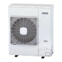
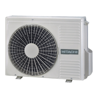
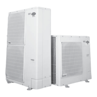
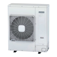
A: Outdoor units.
B: Indoor units.
C: Do not install wiring in a loop.
• Lineconnectionforeachoor.
B
A: Outdoor units.
B: Indoor units.
• Connection with one main line and with the branch lines for the units.
A
B
A: Outdoor units.
B: Indoor units.
! CAUTION
• Themaximumnumberofunitsthancanbeconnectedis64outdoorunitsand160indoorunits(includingUTOPIAand/orSETFREE,
SETFREEMini).
• Donotinstallthewiringinaloop.
• IftheH-LINKIIsystemisnotusedwhencarryingouttheelectricalwiringasshownabove,itmustbeusedoncethewiringofthe
instrumentiscompleted.TheDIPswitchesmustthereforebesetasspeciedintheDIPswitchesonthePCB.

 Loading...


