Do you have a question about the Hitachi V-209 and is the answer not in the manual?
Instrument bandwidth from DC to 20 MHz.
Sensitivity is 1 mV/div.
Internal graticule CRT for parallax-free observation.
Operates via AC line, external DC, or battery pack.
Uses TV sync separator for stable TV signal observation.
Automatically corrects focusing shift.
Lists standard accessories including probes, fuses, power cords, and manual.
Guidelines for temperature, humidity, vibration, and magnetic fields.
Precautions on shock, probes, ventilation, and general handling.
Describes how to position the carrying handle as a tilt-stand.
Instructions for storing the instrument with a dust-proof cover.
Guidance on troubleshooting by rechecking procedures or contacting service.
How to remove stains from the case using neutral detergent.
How to clean the CRT screen to avoid measurement errors.
Details on fuse types, ratings, and replacement precautions.
Checking line voltage range and setting voltage selector.
Information on operating voltage, fuses, and voltage selection.
Options for AC, external DC, and battery pack operation.
Table detailing switch settings for AC, External DC, and Battery Pack modes.
How to operate the V-209 using an external DC source.
How to turn on the instrument and status lamps (POWER, CHARGE).
Adjusting display brightness (INTENsity) and focus.
Aligning trace (ROTATION) and selecting trigger sources (SOURCE).
Switches for selecting AC/DC power and operation mode.
Connectors and switches for vertical axis input and coupling.
BNC connector for CH2 vertical axis input or Y-axis.
Selects signal coupling for the vertical axis amplifier.
Sets the vertical deflection factor or sensitivity.
Fine-tunes vertical deflection sensitivity.
Adjusts the vertical position of the trace.
Selects vertical display modes (CH1, CH2, ALT, CHOP, ADD).
Inverts the polarity of the CH2 input signal.
Sets the sweep time per division.
Calibrates or continuously varies sweep time.
Adjusts horizontal position and activates x10 magnification.
Magnifies sweeps by 10 times for detailed observation.
Selects the trigger signal source (CH1, CH2).
Selecting LINE or external trigger for synchronization.
Terminal for external triggering signals.
Sets the trigger level and slope for synchronization.
Selects trigger modes (AUTO, NORM).
Synchronizing for vertical and horizontal TV signals.
Input terminal for brightness modulation.
Calibration output for probe testing and adjustment.
Earth terminal for the oscilloscope for safety and grounding.
How to operate the oscilloscope using the AD-209 battery pack.
Step-by-step instructions for charging the AD-209 battery pack.
Precautions for battery charging, storage, and lifespan.
Procedure for safely replacing the battery pack.
Recommended initial settings for producing the bright line on the screen.
Settings for observing one waveform using CH1 or CH2.
Settings for observing two waveforms using ALT or CHOP modes.
Settings for operating the oscilloscope in X-Y mode.
Guidelines for using the provided AT-10AK 1.5 probe for measurements.
Warnings regarding input voltage and proper ground lead connection.
Examples of correct and incorrect earth lead wire connections for measurements.
How to adjust the probe correction for accurate measurements.
Precautions for connecting signals directly to the oscilloscope without a probe.
Recommendations for using shielded wires and terminating resistors for wide band measurements.
Step-by-step guide to measuring DC voltage using the oscilloscope.
Guide to measuring AC voltage, including sensitivity and coupling.
How to measure frequency and period using waveform timing on the screen.
Procedure for measuring the time difference between two signal waveforms.
How to measure rise and fall times, considering oscilloscope rise time limitations.
Techniques for achieving stable synchronization with complex signal waveforms.
Using specialized circuits for stable synchronization of TV video signals.
Comparison of synchronization circuits in conventional vs. this oscilloscope.
Procedure for easily adjusting the vertical axis ATT balance.
Recommendations for handling, cleaning, and storing the oscilloscope.
Details on the Cathode Ray Tube (CRT) type, phosphor, graticule, and focus.
Bandwidth, sensitivity, accuracy, and display modes for vertical deflection.
Time base range, accuracy, and magnification for horizontal deflection.
Details on trigger modes, sources, and slope.
Parameters for trigger sources, sensitivity, and level variable range.
Specific parameters for X-Y mode operation, including deflection and bandwidth.
Details of the built-in calibrator, including frequency and output voltage.
Information on voltage and fuse ratings, power consumption, and external DC input.
Limits for operation and storage temperature and humidity.
Physical dimensions and weight of the oscilloscope.
Specifications and charging details for the rechargeable battery pack.
Illustrates the top view of the oscilloscope with key dimensions.
Illustrates the side view of the oscilloscope with key dimensions.
Diagram showing the layout of connectors and controls on the rear panel.
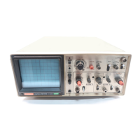
Diagram showing the layout of controls and connectors on the front panel.
Details on voltage references and the low voltage alarm circuit.
Information on power control, input signals, and line voltage shutdown.
Configuration for AC input, DC input, and the AC/DC switching mechanism.
Diagrams showing connections for the battery pack and the charger circuit.
Diagrams illustrating the wiring of various input and output signals.
Instructions for attaching and using the shoulder belt for carrying the oscilloscope.
Instructions for attaching the accessory pouch to the oscilloscope.
| Bandwidth | 20 MHz |
|---|---|
| Channels | 2 |
| Vertical Sensitivity | 5 mV/div to 5 V/div |
| Display | CRT |
| Max Input Voltage | 400 V (DC + AC peak) |
| Time Base Range | 0.2 µs/div to 0.5 s/div |
| Sweep Time | 0.2 µs/div to 0.5 s/div |
| Input Impedance | 1 MOhm || 25 pF |
| Trigger Modes | Auto, Normal |
| Power Supply | 100, 120, 220, 240 V AC, 50/60 Hz |
| Type | Analog Oscilloscope |