10 ELECTRIC WIRING
10.1 GENERAL CHECK
1 Ensure that the eld-supplied electrical components (mains
power switches, circuit breakers, wires, connectors and wire
terminals) have been properly selected according to the
electrical data indicated. Make sure that they comply with
national and regional electrical codes.
2 Following the Council Directive 2004/108/EC (89/336/EEC),
relating to electromagnetic compatibility, next table indicates:
Maximum permissible system impedance Z
max
at the interface
point of the user’s supply, in accordance with EN61000-3-11.
MODEL Z
max
(Ω) MODEL Z
max
(Ω)
RAS-4WHVNPE 0.25 RAS-5WHNPE -
RAS-5WHVNPE 0.25 RAS-6WHNPE -
RAS-6WHVNPE 0.25 RAS-8WHNPE -
RAS-4WHNPE - RAS-10WHNPE -
3 Harmonics situation of each model regarding IEC 61000-3-2
and IEC 61000-3-12 is as follows:
MODELS SITUATION REGARDING
IEC 61000-3-2 AND IEC 61000-3-12
Ssc “xx”
MODELS
Ssc
“xx”
(KVA)
Equipment complying with
IEC 61000-3-2 (professional use)
RAS-(4-6)WHNPE
-
Equipment complying with
IEC 61000-3-12
RAS-(4-6)WH(V)NPE
-
Installation restrictions may be applied
by authorities regarding the power
supply in relation to harmonics
RAS-(8/10)WHNPE
-
4 Check to ensure that the power supply voltage is within
+/- 10% of the rated voltage.
5 Check to ensure that power supply has an impedance low
enough to warranty not reduce the starting voltage more
than 85% of the rated voltage.
6 Check to ensure that the ground wire is connected.
7 Connect a fuse of specied capacity.
? NOTE
Checkandtesttoensurethatifthereismorethanonesourceofpower
supply,thatallareturnedOFF.
! CAUTION
• Checktoensurethatscrewsforterminalblockaretightlytightened.
• Checktoensurethatthetheoutdoorfanhasstoppedbeforeelectrical
wiringworkorperiodicalcheckisperformed.
• Protectthewires,drainpipe,electricalparts,fromratsorothersmall
animals.Ifnotprotected,ratsmaydamageunprotectedparts,andat
theworst,arewilloccur.
• Wraptheaccessorypackingaroundthewires,andplugthewiring
connectionholewiththesealmaterialtoprotecttheproductfromany
condensedwaterandinsects.
• Tightlysecurethewireswiththecordclampinsidetheindoorunit.
• Lead the wires throughthe knockout hole in the side cover when
usingconduit.
• Securethecable of theremotecontrolswitchwith thecord clamp
insidetheelectricalbox.
• Electricalwiringmustcomplywithnationalandlocalcodes.Contact
yourlocalauthorityinregardstostandards,rules,regulations,etc.
• Checkthatthegroundwireissecurelyconnected.
• Connectafuseofspeciedcapacity.
! DANGER
• Donotconnectoradjustanywiringorconnectionsunlessthe
mainpowerswitchisOFF.
• Check that the earth wire is securely connected, tagged and
lockedinaccordancewithnationalandlocalcodes.
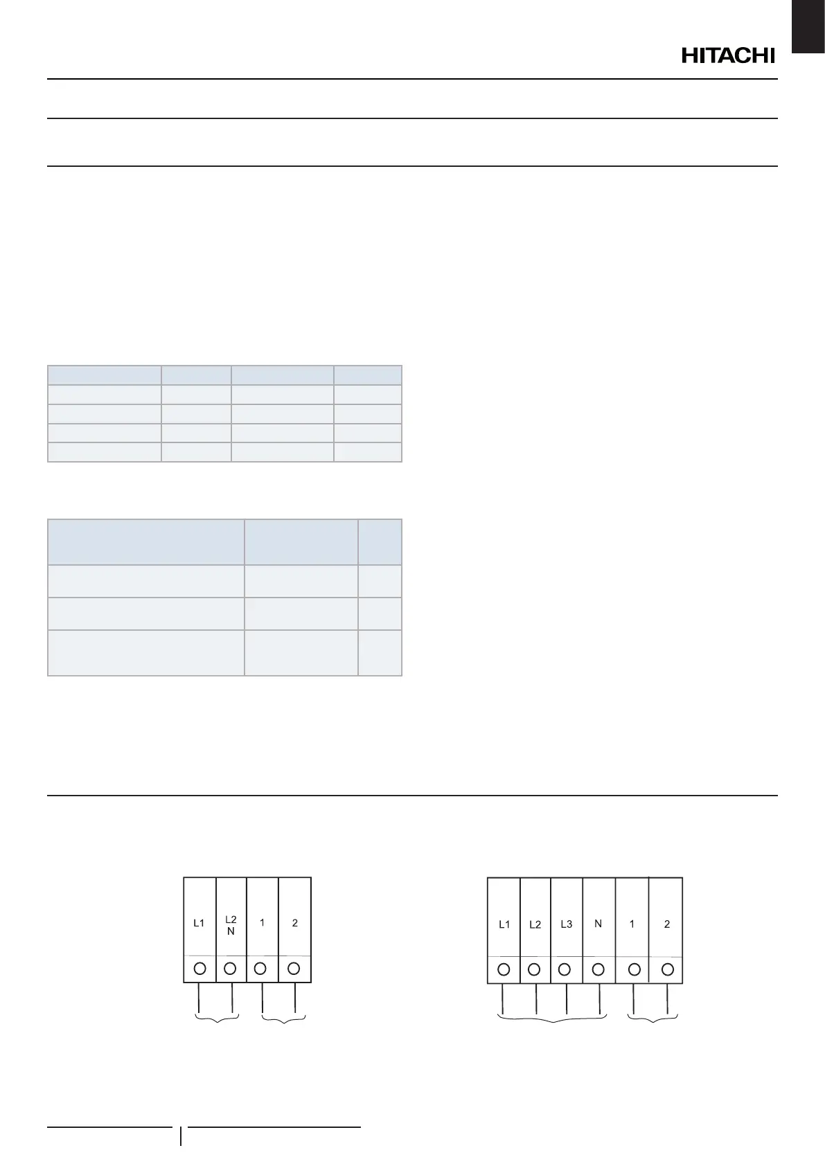
10.2 ELECTRICAL WIRING CONNECTION FOR OUTDOOR UNITS
The electrical wiring connection for the outdoor unit is shown in gure below
RAS-(4-6)WHVNPE RAS-(4-10)WHNPE
Power supply
1~ 230V
Control cable
(5V)
Power supply
3N~ 400V
Control
cable (5V)
ELECTRIC WIRING
PMML0372B rev.5 - 01/2021
13
EN
 Loading...
