This document is a Workshop Manual for the Hitachi ZX 70-3, 70LC-3, 70LCN-3, 75US-3, and 85US-3 Hydraulic Excavators. It is identified by Part No. W1P1-E-00 and is part of a larger Service Manual series that includes Technical Manuals for Operational Principle (Vol. No.TO1P1-E) and Troubleshooting (Vol. No.TT1P1-E).
The manual is structured into several sections covering general information, upperstructure, undercarriage, front attachment, and engine.
Function Description:
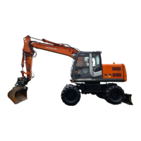
The Hitachi ZX series hydraulic excavators are heavy-duty construction machines designed for various earthmoving and construction tasks. They utilize a hydraulic system for power and control, enabling precise and powerful operation of the boom, arm, bucket, swing, and travel functions. The manual provides detailed instructions for the disassembly, assembly, maintenance, and repair of these excavators, ensuring their proper functioning and longevity.
Important Technical Specifications:
The manual includes critical technical specifications, particularly for tightening torques and painting.
Usage Features:
The manual focuses on maintenance and repair rather than operational usage. However, it implicitly supports safe and efficient operation by providing guidelines for proper assembly and component integrity.
Maintenance Features:
The manual provides extensive guidance on maintenance, emphasizing safety and best practices for disassembly, assembly, and periodic replacement of parts.
-
Safety Information:
- Highlights the importance of recognizing and understanding safety alert symbols (DANGER, WARNING, CAUTION) and signal words.
- Stresses the need to follow recommended precautions and safe operating practices.
- Advises reading and following all safety signs on the machine and in the manual.
- Emphasizes replacing damaged or missing safety signs and manuals.
- Instructs that only trained, qualified, authorized personnel should operate the machine.
- Warns against unauthorized modifications, which can impair function, safety, and void warranty.
- Prohibits the use of unauthorized attachments or optional parts.
- Recommends consulting supervisors or authorized dealers for any questions regarding operation or maintenance.
-
Emergency Preparedness:
- Advises keeping a first aid kit and fire extinguisher on hand, understanding their use, and servicing them regularly.
- Suggests establishing emergency procedure guidelines and posting emergency numbers.
-
Protective Clothing:
- Mandates wearing close-fitting clothing and appropriate safety equipment (hard hat, safety shoes, safety glasses, heavy gloves, hearing protection, reflective clothing, wet weather gear, respirator/filter mask).
- Warns against loose clothing, jewelry, or items that can catch on controls.
- Prohibits wearing radio or music headphones during operation.
-
Noise Protection:
- Recommends wearing suitable hearing protective devices (earmuffs or earplugs) to prevent hearing impairment or loss from prolonged exposure to loud noise.
-
Machine Inspection:
- Stresses daily or shift-based walk-around inspections before starting the machine to prevent personal injury, covering points described in the "RE-START INSPECTION" chapter of the operator's manual.
-
General Precautions for Cab:
- Before entering, remove dirt/oil from work boot soles to prevent slipping on pedals.
- Store parts/tools in specified locations, not around the operator's seat.
- Avoid storing transparent bottles or attaching transparent window decorations that could focus sunlight and start a fire.
- Refrain from listening to radio/music headphones or using mobile phones while operating.
- Keep flammable objects/explosives away from the machine.
- Cover ashtrays after use and do not leave cigarette lighters in the cab due to explosion risk from heat.
-
Precautions for Disassembling and Assembling:
- Cleaning: Thoroughly wash the machine before bringing it into the shop to prevent contamination and damage during assembly/disassembly.
- Inspection: Understand procedures, record machine model, serial number, hour meter, reason for disassembly, leaks, lubricant conditions, and loose/damaged parts.
- Tools and Area: Prepare necessary tools and clean the disassembly area.
- Disassembly: Cap/plug removed pipes, clean components before placing on workbench, drain gear oil, use appropriate fluid containers, use matching marks, use specified special tools, avoid forceful removal of parts, arrange/tag disassembled parts, store common parts carefully, inspect contact/sliding surfaces for wear/damage, and measure/record wear/clearances.
- Assembly: Clean and inspect all parts, repair/replace damaged parts, prevent contamination of contact/sliding surfaces, replace O-rings/backup rings/oil seals with new ones (applying grease before installation), ensure liquid-gasket-applied surfaces are clean/dry, thoroughly clean new parts with anti-corrosive agent, use matching marks, use designated tools for bearings/bushings/oil seals, and count tools after assembly to ensure none are left behind.
- Floating Seal Precautions: Replace floating seals after disassembly; if reusing, keep matched sets together, protect surfaces, apply oil to sliding surfaces, check for scuffing/scoring/corrosion/deformation/uneven wear, check O-rings for tears/breaks/deformation/hardening. Clean seals and mounting bores thoroughly, ensure O-ring is not twisted, and check parallelism of seal ring surfaces after installation.
- Nylon Sling Usage: Follow safety precautions: use protectors on load corners, lower load temperature below 100°C (212°F), avoid lifting acid/alkali chemicals, keep slings dry, use slings of same width/length for multiple slings, eliminate gaps when lifting with eyeholes (reduce load weight to <80% of breaking force), avoid twisted/bound/connected/hitched slings, do not place objects on twisted/bent slings, avoid damaging slings when removing/dragging, protect joints when using with other sling types, and store slings indoors. Visually check slings for damage (broken sewing thread, scuffing, fuzz, separation of belt, broken warp) before use; discard damaged slings or slings older than 7 years.
-
Bleeding Air from Hydraulic System:
- IMPORTANT: Bleed air before starting the engine to prevent damage to the pump, motor, or cylinder.
- Hydraulic Pump: Remove the plug, fill the pump housing with hydraulic oil, temporarily tighten the plug, start the engine at slow idle, slightly loosen the plug until oil oozes out, then securely tighten.
- Travel Motor / Swing Motor: Remove the drain plug/hose, fill the motor case with hydraulic oil.
- Hydraulic Circuit: After refilling, start the engine, operate each cylinder, swing motor, and travel motor evenly under light loads for 10-15 minutes (slowly, not full stroke initially). Pilot oil circuit air will bleed automatically. Reposition front attachment, stop engine, recheck, and replenish hydraulic oil.
-
Service Recommendations for Split Flange:
- Clean and inspect sealing surfaces for scratches/roughness/unevenness; replace components if defects cannot be polished out.
- Use only specified O-rings, inspect for damage, and apply grease when installing.
- Ensure split flange halves are centered and perpendicular to the port, hand-tighten bolts, and avoid pinching O-rings.
- Tighten bolts alternately and diagonally; do not use air wrenches, as they can cause uneven tightening and O-ring damage.
-
Nut and Bolt Locking:
- Lock Plate: Do not reuse lock plates or bend the same point twice.
- Cotter Pin: Do not reuse cotter pins; match holes in bolt and nut while tightening.
- Lock Wire: Apply wire in the bolt-tightening direction, not loosening direction.
-
Connecting Hose:
- CAUTION: Use only genuine Hitachi service parts to prevent oil leaks, rupture, or separation, which could lead to fire.
- Do not install kinked hoses, as high pressure, vibration, or impact can cause leaks or rupture. Use print marks to prevent kinking.
- Protect hoses from rubbing against each other or moving/sharp parts to prevent wear and rupture.
-
Periodic Replacement of Parts:
- Emphasizes periodic inspection and replacement of parts that, if defective, pose safety/fire hazards and whose deterioration is hard to gauge visually.
- Every 2 years: Fuel hose (tank to supply pump), oil filter hose (engine to oil filter), heater hose (heater to engine), pump suction hose, pump delivery hose, swing hose, travel high pressure hose, boom cylinder line hose, arm cylinder line hose, bucket cylinder line hose.
- Every 3 years: Seat belt.
- Every 5 years: Clear hatch (if equipped).
- Note: Replace seals (O-rings, gaskets) when replacing hoses.