9
Nominal cooling capacity (kW) of one circuit
Pressure drop per 10 m. of equivalent length
Suction / discharge line. Vertical
pipe run - Fig. 3
- For heat pump systems use a trap
at the base of the vertical pipe run.
- There is no need for intermediate
trap.
- For cooling only systems traps are
not required.
- For heat pump systems keep veloc-
ity in the vertical run of suction or
discharge line more than 6 m/s.
For both options the following condi-
tions should be observed:
- The maximum allowable speed in all
gas lines is 15 m/s.
- The suction line must have insula-
tion and a slope of 1-2% toward the
compressor in the horizontal pipe
run.
- For long piping run it may be neces-
sary to adjust oil charge (see table
2). For each trap and for 10 m. of
pipe above 20 m. add oil.
- In the case of downward liquid flow
with a height exceeding 10 m. it is
necessary to install a manual pres-
sure equalization valve.
- Keep liquid subcooling at least 1°C
at the restrictor inlet. If the liquid
line has upward flow and pipe
length exceeding 15 m., for each 3.5
m. above this value provide 1°C
subcooling. In the cooling systems
subcooling can be obtained by the
contact of liquid and suction line (on
a max. length of 15 m.) creating the
heat exchange.
- For every meter of piping installed
add refrigerant according with the
table 1.
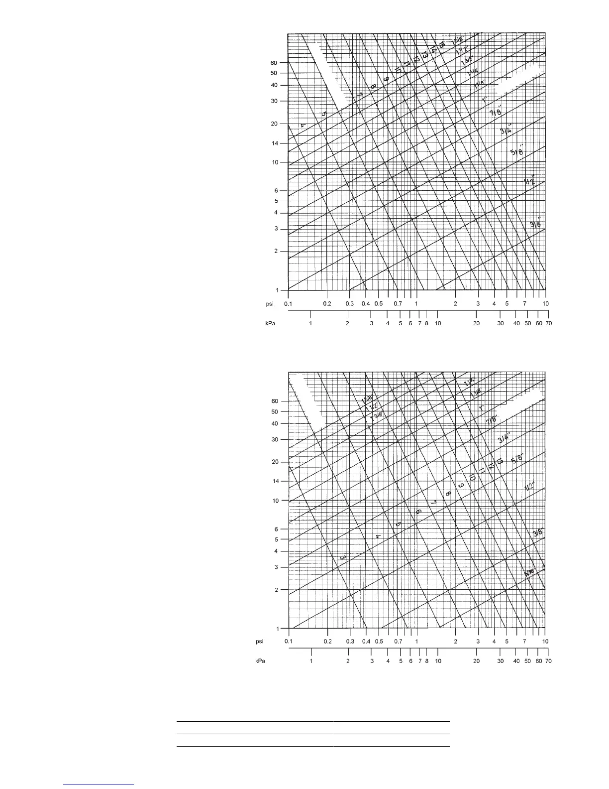
Graph 1 - Suction line
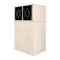
Nominal cooling capacity (kW) of one circuit
Diameter
Speed m/s
Pressure drop per 10 m. of equivalent length
Graph 2 - Discharge line
Speed m/s
Diameter
Table 2: ADDITIONAL OIL CHARGE
Diam. 3/8" 1/2" 5/8" 3/4" 7/8" 1-1/8" 1-3/8" 1-5/8"
cm³/10m 1.5 3 5 9 16 35 54 80