Do you have a question about the HiTi Digital S400 and is the answer not in the manual?
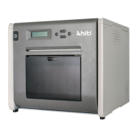
Introduces the HiTi Photo Printer S4XX SERIES, its features, and operation modes.
Details the technical specifications of the HiTi Photo Printer S4XX SERIES.
Lists parts and their corresponding part numbers for S400 and S420 models.
Explains the D2T2 printing technology used in the printer.
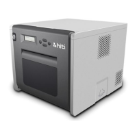
Introduces the hardware components of the printer.
Describes the Thermal Print Head (TPH) as a key component of D2T2 printers.
Details the Main Board and its ASIC, including its functions and memory sockets.
Explains the Power Board, its inputs/outputs, and its role in adjusting THP voltage.
Describes the TPH Boards (L and R) connecting sensors, fan, and TPH to the motherboard.
Details the Controller Board, its CPU, EPROM, and function in central control.
Explains the Cam Motor's function in controlling platen and pinch roller positions.
Describes the Capstan Motor's role in paper movement and ribbon rewinding.
Explains the Ribbon/ ADF Motor's function in feeding paper and advancing the ribbon.
Describes the Status/ Error LED and its indication of printer status and errors.
Details the Cam Sensor's function in detecting platen roller positions.
Explains the LE Sensor, Jam Sensor, and Back Door Sensor for paper and door status.
Describes the Ribbon LED and Sensor for detecting ribbon color and type.
Explains the Ribbon Cassette Sensor for detecting ribbon cassette status and type.
Details the Ribbon Door Sensor for detecting if the ribbon door is open or closed.
Explains the Fan's role in reducing the temperature of the Thermal Print Head (TPH).
Introduces the mechanical components of the printer.
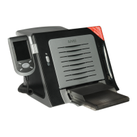
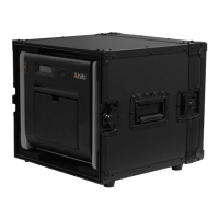
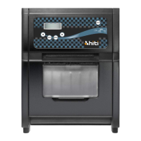
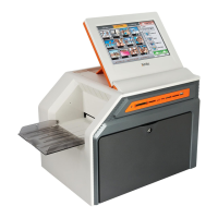
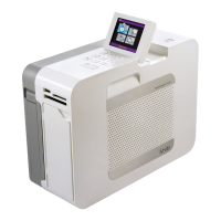
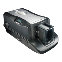
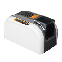
Shows the printer profile and identifies user-accessible components like Door Button and Paper Cassette.
Explains the three motors (ADF, Capstan, Cam) used for driving the ribbon, paper, and cam position.
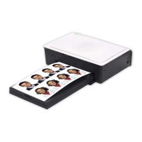
Details the mechanism for feeding paper from the cassette to the printer.
Explains the mechanism responsible for rotating the ribbon.
Describes how the Capstan Motor drives paper movement, including forward, backward, and exit.
Explains how gear sets and cams control platen and pinch roller positions.
Covers firmware updates and initialization processes.
Guides on updating the printer's firmware using BurnFW.exe.
Describes the printer's initialization process upon power-on.
Lists error messages indicated by the Status LED and their solutions.
Provides essential safety precautions before disassembling the printer.
Lists the necessary tools for disassembly.
Identifies parts that should not be disassembled due to calibration requirements.
Provides a comprehensive list of parts that can be disassembled.
Details the disassembly of the Controller Board and its cable.
Explains how to disassemble the ribbon door and front case.
Details the procedure for removing the back case of the printer.
Guides on disassembling the Power Board and Sheet_Power_Board.
Details the process of removing the Main Board.
Explains disassembly of TPH Boards, Fan, and Ribbon LED_B.
Details the removal of ADF, Cam, and Capstan Motors.
Guides on disassembling the Status LED.
Explains the procedure for removing the Cam Sensor.
Details the disassembly of the Cover Open Sensor.
Guides on removing the Jam Sensor.
Explains the removal of Ribbon Sensor_B, LE Sensor, and Tray Front.
Details the disassembly of Cassette Sensor and Ribbon Sensor_F.
Guides on removing the Capstan Roller and Pinch Roller.
Details the procedure for removing and assembling the Thermal Print Head (TPH).
Explains the disassembly and removal of the TQL component.
Provides safety precautions for performing adjustments.
Lists the tools required for performing adjustments.
Details how to adjust VR on the Main Board for voltage output.
Guides on adjusting VR on the Power Board for voltage and color density.
Explains how to re-adjust and re-align gears for cam/platen errors.
Describes ECR/ECN changes related to S420 LCD and Controller Board compatibility.
Provides contact details for HiTi Digital in various regions.
| Brand | HiTi Digital |
|---|---|
| Model | S400 |
| Category | Printer |
| Language | English |