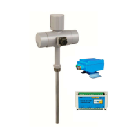
The HITROL HCC-95P Series is a capacitance type level switch designed to detect the level of various mediums by sensing changes in capacitance values, which are influenced by the dielectric constant of each medium.
Function Description
The device operates on the principle that when an air surrounding the electrode probe is replaced by another medium, the capacitance value changes according to the medium's dielectric constant. As the electrode probe comes into contact with the medium, the capacitance value increases, prompting the level switch to activate a relay output by converting the changed capacitance value into an electronic signal.
The HCC-95P(-Ex) Series offers several key features:
- Versatile Application: Widely used for various mediums, including solids, powders, and liquids.
- Durability: Features a semi-permanent life cycle due to its moveless parts.
- Corrosive Liquid Compatibility: Easy to use in corrosive liquid environments.
- Ease of Installation: Simple installation, especially for wire-type models (HCC-95PW).
- On-site Operation Check: Allows for direct verification of operation at the installation site.
- Adaptable Probe Types: Various probe types can be applied to suit different installation conditions.
- Safety Certifications: Available in explosive-proof (HCC-95P-Ex) and dust-proof versions.
Important Technical Specifications
The HCC-95P Series comes in Weather-proof (IP65) and Ex-proof (IP66) versions, with different models tailored for specific applications.
General Specifications (Weather-proof Version):
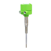
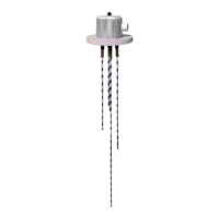
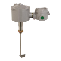
- Probe Type: Rod (Flat) or Rope.
- Mounting: Screw or Flange.
- Ambient Temperature: -20°C to +60°C.
- Process Temperature:
- Rod (Flat): -40°C to +80°C (HCC-95P), -40°C to +150°C (HCC-95PH).
- Rope: -40°C to +80°C (HCC-95PW), -40°C to +150°C (HCC-95PWH).
- Process Pressure: Vacuum to 20kg/cm² (300#).
- Power Source: AC 90-240V, 50/60Hz (Std.) / DC +24V (Opt.).
- Output Signal: DPDT (Double Pole Double Throw).
- Contact Rating: AC 250V, 5A / DC 30V, 5A.
- Enclosure: Weather-Proof (IP65).
- Wetted Parts Material: SUS 304, 316L with Teflon (Peek) for Rod (Flat); SUS 304, 316L with Teflon for Rope.
- Process Connection: PT 1"(M) Screw.
- Housing; Cable Entry: PBT;PF1/2"(F), IP65 or AL;PF1/2"(F), IP66.
Ex-proof Version (Additional Specifications):
- Enclosure: Ex d IIC T5/T6(), IP66 or Ex d IIC T3/T4(), IP66.
- Ex tb A21 IP66 80°C or Ex tb A21 IP66 150°C.
- (*) Explosion-proof Fluid Temp. & Grade: Max. 70°C for T6, Max. 80°C for T5, Max. 130°C for T4, Max. 150°C for T3.
Amplifier Specification (M-95P Module):
- Microprocessor: 16Bit Microprocessor.
- Power Consumption:
- AC: Stand-by 3.1W (110V) / 7W (220V), Active 3.9W (110V) / 7.6W (220V).
- DC: Stand-by 0.2W (24V), Active 0.96W (24V).
- Oscillation Frequency: 1MHz.
- Sensitivity Resolution: 0.1pF.
- Dielectric Constant: 2 @ Min.
- Function (Adjustment): Sensitivity, Relay Delay Time, Relay Return Time, Relay Contact Control (Normal/Reverse).
- Sensitivity Setting Range: 10pF ~ 150pF (BCD Dip Switch method).
- Fine Sensitivity Adjustment (SEN.): Dry Contact: △10pF, Wet Contact: △-5pF.
- Relay Delay/Return Time Range: 0.5Sec. @ Min / 1Sec. ~ 10Sec. @ 0.1Sec. Resolution.
- Relay Contact Out Control: Normal Close @ Default.
- Status Indicator: Bi-Color LED [Green / Red / Orange] for status, Red LED for detection, Green LED for relay control.
- UART: Monitoring.
- Ambient Temperature (Module): -20°C ~ 80°C.
Dimensions & Technical Data:
- Housing: PBT or Aluminum, with various connection types (Screw: PT 1", NPT 1", PF 1"; Flange: ANSI, JIS, DIN; Tri-Clamp).
- Probe Lengths:
- Rod Probe: Total length 100~2,500mm, Active Rod Length 100~1,000mm, Inactive Rod Length ~1,500mm.
- Fully Insulated Rod Probe (w/ TEFLON): Total length 300~1,000mm, Active Rod Length 150~500mm, Inactive Rod Length 150~500mm.
- Rope Probe: Min. 1,000mm, Max. 10,000mm.
- Probe Diameters:
- Active Rod dia.: Φ15 (including Teflon).
- Inactive Rod dia.: Φ25.4.
- Fully Insulated Rod Probe (w/ TEFLON): Active Rod dia. Φ28 (including Teflon), Inactive Rod dia. Φ28 (including Teflon).
- Rope Probe Weight: 170g (≤2,500mm), 300g (≤4,500mm), 300g (>4,500mm).
- Dielectric Constant Values: A table of common mediums and their dielectric constants is provided (e.g., Air: 1, Water: 81, Sulfuric Acid: 84).
Usage Features
Installation Precautions:
- Can be installed via screw (PT, NPT, PF, etc.) or flange (ANSI, JIS, DIN, etc.) and tri-clamp.
- Side Mounting: Recommended for high sensitivity, install slopingly (15 degrees to horizontal) with the sensor forwarding to the bottom to prevent malfunction from medium build-up. Inactive rod should be at least 50mm inside the tank. Cable entry should face the ground for waterproofing.
- Top Mounting: Less affected by medium build-up, but lower sensitivity as it measures only by the end of the probe. Not suitable for low dielectric constant mediums.
- Multiple Units: Maintain at least 300mm distance between probes to avoid unstable operation.
- Protection: Install probe to avoid inlet side and use a protector to prevent damage from incoming medium.
- Liquid Mediums: Set Time Delay appropriately to delay relay operation.
- Outdoor Installation: Install a sun cover to mitigate temperature effects.
- Stirred Tanks: Install probe at a safe distance from the stirrer.
Wiring Precautions:
- Avoid shaking or obstacles during sensor installation.
- Do not install in areas prone to severe fluid flow, mechanical damage, or chattering.
- Verify temperature and pressure specifications inside the tank.
- Dehumidifier (gortex) or ventilation may be needed if housing temperature differs significantly from ambient temperature.
- Connect flanges/bolts with matching specifications and ensure gaskets are inserted correctly.
- For Ex-proof products, install with appropriate grade for the environment.
- Connect AC (90-240V) or DC (+24V) power correctly, observing polarity for DC.
- Do not connect wires with power supplied.
- Provides DPDT output by default; wire COM and N.O terminals for high alarm.
- External grounding is required.
- For Ex-proof products, apply power only after tightening the cover after wiring.
M-95P Configuration and Function (Module Settings):
- SET (1): Autoset for automatic capacitance measurement and standard setting.
- RANGE (2): Sets capacitive measurement sensitivity range (10pF ~ 150pF) via BCD Dip Switch.
- SEN (3): Fine tunes sensitivity (Dry Contact: △10pF, Wet Contact: △-5pF).
- DT (4): Adjusts relay delay time (0.5s, 1s ~ 10s @ 0.1s resolution).
- RT (5): Adjusts relay return time (0.5s, 1s ~ 10s @ 0.1s resolution).
- Fail Safe Mode (6): Relay transformation adjustment (N.C ↔ N.O).
- DET (7): Measurement status LED (OFF → Red).
- RLY (8): Relay status LED (N.C: OFF → Green, N.O: Green → OFF).
- PWR (9): Power & status display.
- UART (10): M-95P status setting and communication port.
- Power (11): Power connector (AC / DC).
- Relay Out (12): Relay contact out (DPDT).
Setting and Adjustment:
- Initialization: After installation, set to initial state for quick response.
- Tuning Setting 1 (Autoset then Sensitivity Adjustment):
- Press SET tact switch for 1 second (PWR LED turns on/off) to automatically measure capacitance and set reference value.
- Adjust sensitivity for the measuring medium using SEN. VR.
- Tuning Setting 2 (Autoset after Sensitivity Adjustment):
- Adjust sensitivity using SEN. VR.
- Press SET tact switch for 1 second to automatically measure capacitance and set reference value.
- Adjust Sensitivity (Dry Contact): If the medium is not in contact, adjust sensitivity using SEN. VR.
- Adjust Sensitivity (Wet Contact): If the medium is in contact, adjust sensitivity using SEN. VR.
- Sensitivity Setting and Fine Adjustment Area: A detailed table maps RANGE settings (10pF to 150pF) to corresponding SEN. (fine adjustment) ranges for both wet and dry contact, indicating sensitivity levels.
- Relay Operation Time Adjustment: Adjust relay delay time (DT) after detection and relay return time (RT) after undetecting the medium.
- Adjust Fail Safe Mode: Configure relay contact status to N.C (default) or N.O.
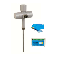
UART Monitoring:
- Allows checking adjusted settings via PC or Smartphone (Password: 1975).
- Components: PC, USB Cable (USB to Micro USB B), UART ADAPTOR.
- Displays sensor measurement status, sensitivity settings, relay settings, etc.
- Smartphone monitoring requires "Serial USB Terminal" app, setting Baud rate to 9600, disabling connection messages and timestamps, and configuring Send/Receive Newline and Character delay.
Maintenance Features
Failure Check & Maintenance:
- Regular inspection (at least annually) is crucial for optimal performance.
- Visually check for damage and regularly remove medium build-up or foreign substances from the sensor, being careful not to damage the Teflon part.
- Failure Check Steps:
- Verify correct power voltage connection.
- Confirm power voltage supplied matches specifications.
- Check cable wiring.
- Verify Fail-Safe Mode setting.
- Check if the green LED is on.
- WARNING: Turn off power for maintenance. In an explosion area, do not disassemble when power is applied.
Precautions for Removal:
- Check the level and presence of the measured object in the tank before removal.
- Wear gloves to prevent burns.
- Unlock the lock key before removing the cover (Ex-proof).
- Disassembly must be done with power off.
- Ensure O-rings or gaskets are not damaged when opening/closing the cover.
- CAUTION: Avoid high impact during movement.
- WARNING: In an explosive gas atmosphere, do not open the product cover.
Precautions for Use:
- Ensure the product is appropriate for the Ex-proof zone if applicable.
- Do not bend or extend the sensor randomly.
- Install the product and cover completely before supplying power.
- Do not use if the installation temperature range exceeds -20°C to +60°C.
- Do not use if a higher protection grade than the product's (IP66 for AL. Housing or IP65 for PBT Housing) is required.
- Avoid use in vibrating environments.
Precautions for Inserted External Wire (Ex-proof):
- Use cable gland connection or metal pipe line lead-in for wire inlet.
- Connect with an external line lead-in method using a product with equivalent Ex-proof certificate.
- For unused external wire inlets, use a closed plug that meets safety certificate standards equivalent to the product's performance.
Precautions for Grounding (Ex-proof):
- Both external and internal grounding are required.
- External ground wire should be 4mm² (4mmSQ).
- Internal grounding should match the connected cable's specification.
- WARNING: Ensure a washer is inserted if the terminal lug is removed and reconnected to prevent loosening.
Safety and Environment:
- Connect the product and vessel using appropriate tools.
- Keep the lock key safe and ensure it is locked.
- Avoid high impact to the product.
- Connect contacts to correct terminals (refer to Wiring).
- Wire and supply power after checking specifications. Incorrect voltage can damage the product.
- Take precautions to prevent electric shock.
- Disposal: Separate amplifier and main unit from housing before disposal. No parts (e.g., Mercury switch) have environmental impact requiring special attention.
User Training:
- Fluid temperature in the tank should not exceed 80°C for general type and 150°C for high-temperature type.
- Ambient temperature of housing must be kept between -20°C and +60°C.
- For explosion-proof products, never open the cover during use. These products comply with industrial safety and health regulations.
- WARNING: Do not use non-ex-proof products in Ex-proof zones. Ex-proof products can only be installed in Zone 1 and 2 locations with explosive gas atmospheres, adhering to ex-proof temperature ratings and fluid temperatures.
Warranty and Contact:
- Product is covered by a 2-year warranty from shipment date for damages under normal operating conditions. Service charges apply for non-product failure issues.
- Contact HITROL CO., LTD. headquarters for A/S or visit their website.